SD-Access Cisco DNAC Design Steps Configuration Dashboard ver 2.2.3.x
23.06 2023 | by massimilianoSD-Access Cisco DNAC Design Step Configuration Dashboard ver 2.2.3.x Di seguito un elenco ordinato di steps che prevedono la configurazione […]
https://www.ingegnerianetworking.com/wp-content/uploads/2023/06/dnac1-90b.png
SD-Access Cisco DNAC Design Step Configuration Dashboard ver 2.2.3.x
Di seguito un elenco ordinato di steps che prevedono la configurazione programmata del DNA Center.
DNAC Network Design
Create Network Site
Step-1: navigate to DESIGN > Network Hierarchy
Step-2: click Add Site > Add Area > Area Name and then click Add
Step-3: click Add Site > Add Building > Building Name, select the site created in step-2 as the Parent and complete the wizard to assign a location, and then click Add
Step-4: Repeat the step-3 as required to adds sites and buildings
Step-5: for integrating wireless to a building or require more granularity for network choises within a building, select the building on the map, choose Add Floor and complete the wizard with own details.
Nota:
Floors sono riferiti durante il wireless provisioning dove gli AP sono assegnati al building floor.
Network Services: AAA, DHCP, DNS
Step-1: navigate to DESIGN > Network Settings > Network > within the left pane in the site hierarchy, select the appropriate level (ex Global), fill the follow details:
- DHCP Server IP address
- DNS Server: Domain Name and IP primary address (and any redundant additional server; it is possible leave the default selection to use Cisco DNA Center for the Syslog and SNMP)
- Save
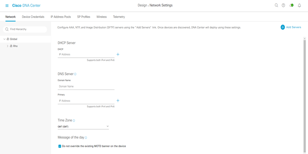
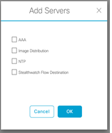
Step-2: click the Add Servers and select the AAA and NTP check boxes and click OK.
Step-3:
- under AAA select the Network and Client/Endpoint check boxes
- under NETWORK select the Server ISE button
- under NETWORK use the pull-down to select the prepolutated ISE server
- under NETWORK select the protocol TACACS button
- under NETWORK select the IP address primary and additional tacacs server
- under CLIENT/ENDPOINT select the Server ISE button
- under CLIENT/ENDPOINT select the protocol RADIUS
- under CLIENT/ENDPOINT select the IP address primary and additional radius server
Step-4:
Select the NTP server add the IP address and if you have, also the ip address of additional NTP server, then click save
Device Credential
Step-1: navigate to DESIGN > Network Settings > Device Credential > within the left pane in the site hierarchy, select the appropriate level (ex Global), fill the follow details:
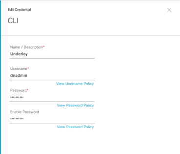
Step-2: select the follow detail on CLI
- Name/Description: Underlay
- Username: dnadmin
- Password: password
- Enable Password: password
Save
Nota:
Best Practices Cisco indicano, in caso di utilizzo di ISE come server AAA, di evitare “admin” come username perché causa di eventuale conflitto con il login di ISE, rendendo cosi inagibili i devices stessi.
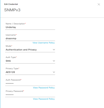
Step-3: select la modalità SNMPv3 and then fill the follow details:
- Name/Description: Underlay
- Username: dnasnmp
- Mode: Authentication and Privacy
- Auth Type: SHA
- Privacy Type: AES128
- Auth Password:
- Privacy Password:
Save
IP Pool Gloabl Address
Le opzioni possibili di settare un IP Pool address è manuale attraverso il DNAC oppure inserire gli IP addressess gestiti attraverso un sistema quale IPAM via API.
In questo ultimo caso è necessario navigare dal menu: Design > Network Settings > IP Address Pool > Import > Import from IPAM server
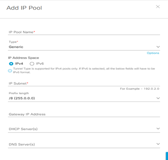
Step-1: navigate to DESIGN > Network Settings > Device IP Address Pool > within the left pane in the site hierarchy, select the appropriate level (ex Global), click the Add button and fill the follow details:
- IP Pool Name:
- Type:
- IP Address Space: set IPv4
- IP Subnet:
- Prefix lenght:
- Gateway IP Address:
- DHCP Server(s):
- DNS Server(s):
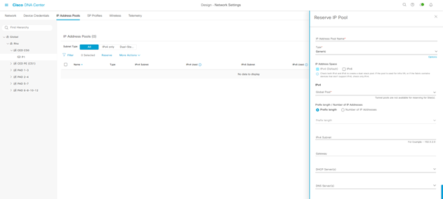
Reserve IP Pool Address
Step-1: navigate to DESIGN > Network Settings > Device IP Address Pool > Reserve within the left pane in the site hierarchy, select the appropriate level (example Global), click the Add button and fill the follow details:
- IP Pool Name:
- Type:
- IP Address Space:
- IP Subnet:
- Prefix lenght:
- Gateway IP Address:
- DHCP Server(s):
- DNS Server(s):
Step-2: Ripetere le operazioni suddette per ogni nuovo blocco di IP address pool da riservare per ciascun sites.
Fabric Enterprise Wireless SSID
Step-1: navigate to DESIGN > Network Settings > Wireless > within the left pane in the site hierarchy, select the appropriate level (example Global), click the Add button and fill the follow details:
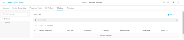
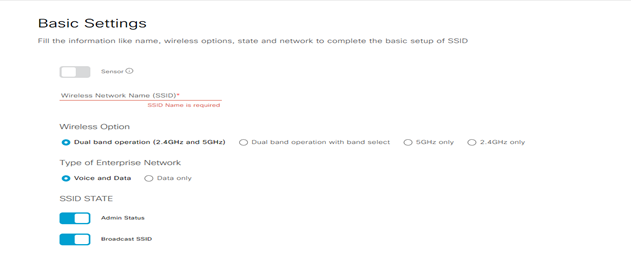
Step-2: create Enterprise wireless network and fill the follow details:
- Wireless Network Name (SSID)
- Wireless Option (dual-band operation; dual-band operation with band select; 5GH only; 2,4 GHZ only):
- Type of Enterprise Network (Voice and Data; Data only):
- SSID State (Admin Status; Broadcast SSID)
Step-3: click next to continue:
- Wireless Profile Name:
- Fabric: YES
- Choose a site: select the location where the SSID broadcast and include floors to include SSID coverage
- SSID State (Admin Status; Broadcast SSID)
Finish
Fabric Guest Wireless SSID
Step-1: navigate to DESIGN > Network Settings > Wireless > within the left pane in the site hierarchy, select the appropriate level (ex Global), click the Add button and fill the follow details:
Step-2: create Guest wireless network and fill the follow details:
- Wireless Network Name (SSID)
- Wireless Option (dual-band operation; dual-band operation with band select; 5GH only; 2,4 GHZ only):
- Type of Enterprise Network (Voice and Data; Data only):
- SSID State (Admin Status; Broadcast SSID)
Step-3: click next to continue:
- Wireless Profile Name:
- Fabric: YES
- Choose a site: select the location where the SSID broadcast and include floors to include SSID coverage
- SSID State (Admin Status; Broadcast SSID)
Finish
Cisco DNA Center administrative login in ISE
Step-1: Login in ISE platform and navigate in Administration > Identity Management > Identities > Add
- Name: (matching quello usato per il DNA Center discovery e differente dall’ISE administration)
- Login Password:
- Re-Enter Password:
- Submit
User login è quindi disponibile da ISE e lo stesso user ID è creato per ogni devices discoverato utilizzando Lan Automation
L’integrazione tra ISE e DNAC deve seguire importanti step quali:
Assicurarsi che le versioni software di entrambi i servizi siano compatibili
Cisco Software-Defined Access Compatibility Matrix
- Enable pxGRID almeno in un nodo ISE deployment; si raccomanda si assegnare un pxGrid Persona in deploymen. pxGrid service in connected status tab ISE web interface;
- DNAC usa ERS API per write and read policy configuration in ISE; pre-requisito ERS (External RESTful Services) deve essere abilitato su ISE. In un deployment distributed ERS write/read necessità di essere abilitato in un nodo PAN per
- configurazione emantenimento del database (altri nodi debbono avere ERS con read-only permission);
- Assicurarsi che CLI e web interface username e password in ISE abbiano le stesse credenziali; DNAC utilizza le stesse credenziali per il login in CLI e web interface di ISE.
- Assicurarsi che tra il DNAC ed ISE siano aperte le comunicazioni TCP ports 22,443,5222,8910 e 9060.
- Dal punto di vista del DNAC, ISE è integrato come un Authentication and Policy Server
Step-2: Login in DNAC e navigate to System > Settings > Authentication and Policy Server > Add
Enter:
- Server IP address: ip address of ISE PAN deployment (with must interface Gig0)
- Shared Secret: chiave tra network devices e ISE policy server
- Username: username to log in ISE with SSH and GUI
- Password: password to log in ISE with SSH and GUI
- FQDN: fully qualified domain name associated with Gig0 in ISE primary node
- Subscriber Name: usato per identificare il DNAC client name in ISE
- SSH Key (optional):
- Virtual IP address (optional): se ISE policy node dovesse essere dietro Load Balancer
In advanced settings:
- Protocol: enable RADIUS or TACACS
- Authentication Port: port used for Radius Server (default = 1812)
- Accounting Port: port used for Radius Server (default = 1813)
- Port: port used for Tacacs Server (default = 49)
DNAC Segmentation and Policy Process.
In SD-Access Macro-Segmentation è riferita alla configurazione di VN overlay (Virtual Network) mentre Micro-Segmentation è riferita alla configurazione di SGT (Scalable Group Tag) applicate alle policies dedicate per users oppure device profiles.
VNs
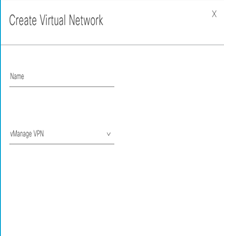
Step-1: navigate to Provision > Virtual Networks > Create Virtual Network +
L3-VN Overlay to SD-Access Network
Step-1: navigate to Workflows > Create Layer 3 Virtual Networks > and follow the process:
- Choose your creation process: how many L3 VNs would you like to create for the fabric? enter a value
- Create your Layer 3 Virtual Network
- Select your Fabric Sites
- Configuring traffic exit behavior
Di default Local Exit è selezionato (questo permette al traffico di uscire attraverso un local border associato a quel fabric site);
choose Remote Exit, in caso di uscita del traffico da un designated border
- Summary
- To create the context of VN, click Create
- To assign the VN to the selected sites, click Deploy
- To verify the VN creation, click View All Virtual Networks
VN con associazione ad un determinato gruppo è visto in una lista di virtual networks ed esse sono disponibili per il provisioning fabric
Nota: se le VN non dovessero essere vista nella lista, è probabile un problema tra DNA Center ed ISE; in questo caso rivedere la procedura di integrazione per ISE ed assicurarsi che il pxGrid sia abilitato in ISE per il DNA Center.
In caso di definire più gruppi differenti, rispetto al gruppo di default, è necessario creare gruppi customizzati attraverso la seguente procedura:
Step-2: navigate to Policy > Group-Based Access Control > Security Groups > Create Security Groups
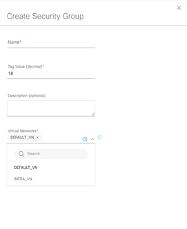
Step-3: ripetere i primi due step per ogni overlay network.
Per wireless user che richiedono a “guest service” è necessario creare una Guest VN per supportare questa funzionalità.
L2-VN Overlay to SD-Access Network
Step-1: navigate to Workflows > Create Layer 2 Virtual Networks > and follow the process:
- Configure VLANs: how many VLANs would you like to connect to the fabric? enter a value
- Configure VLANs
Vlan Name:
Vlan ID:
Traffic Type (Data or Voice):
- Select your Fabric Site for each Layer 2 Virtual Network
- Summary
- Create
- Submit
- Success! You’ve created a task to deploy a Layer 2 Virtual Network
Micro-Segmentation SGT Policy
ISE Security Groups sono lo stesso di Scalable Groups in DNAC con le seguenti caratteristiche:
- Name and SGT value deve essere lo stesso in ISE e DNAC (stesse informazioni coerenti);
- Se un ISE security group con SGT value non esiste in DNAC, un nuovo scalable group è creato in DNAC;
- In caso di non match del name security group (con stesso SGT value), il nome di ISE security group sostuisce il nome presente in DNAC;
- In caso di non match del SGT value (con stesso name) il nome ed il SGT value in DNAC viene rinominato con l’aggiunta di un suffisso “_DNA”;
I contract in ISE sono chiamati SGACLs referenziate da policies, mentre in DNAC sono conosciuti come “Access Contracts” e seguono le seguenti caratteristiche:
- SGACLs ed access-contract con stesso nome e contenuto hanno informazioni coerenti
- Se SGACLs ed Access-contracts hanno stesso nome ma contenuti differenti, il contenuto del contratto in DNAC viene scartato;
- Se il name di un SGACLs non esiste in DNAC, un nuovo access-contracts con lo stesso nome viene creato ed il contenuto viene cosi migrato da ISE a DNAC.
Le policy sono unicamente identificate da la coppia source e destination group.
ISE TrustSec Egress Policy Matrix policies sono comparate con le policies del DNAC e seguono le seguenti caratteristiche:
- Situazione coerente con stesse policies source and destination group tra SGACLs ed access-contract
- Se una policy per un source-destination group è differente, ISE sovrascrive la propria policy nel access-contract del DNAC;
Create Policy:
Step-1: navigate to Policy > Group-Based Access Control > Policies > Create Policies
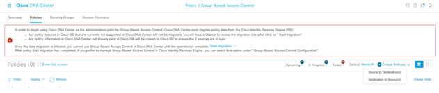
Set Source to Destination(s) and then from Policies
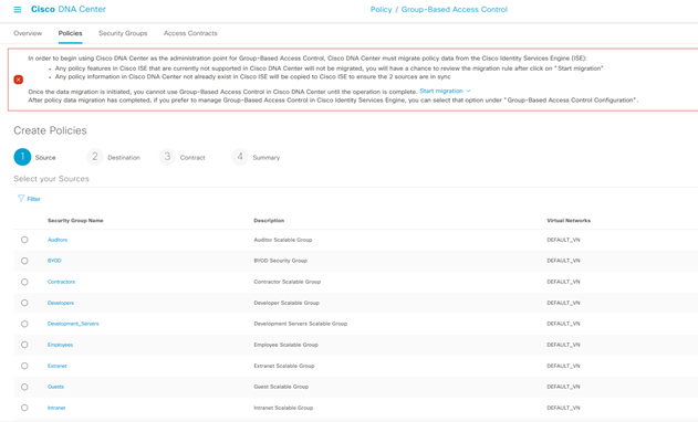
Filter the Source Policies created.
Set Destination to Source(s) and then from Policies
Select the Destinations
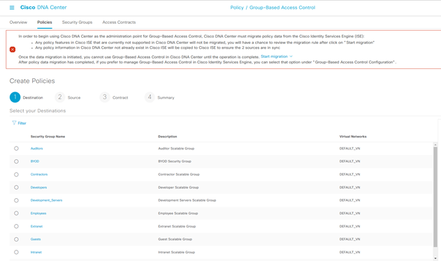
Enter:
- Description
- Enable Policy
- Enable Bi-directional
Create Contract:
Step-2: navigate to Policy > Group-Based Access Control > Access Contracts > Create Access Contract
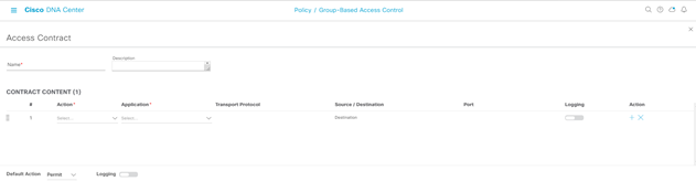
Enter:
- Name:
- Description:
- Contract Content Action (Permit or Deny):
- Contract Content Application:
- Transport Protocol:
- Source/Destination:
- Port
- Logging
- Action:
- Default Action (Permit or Deny):
- Logging
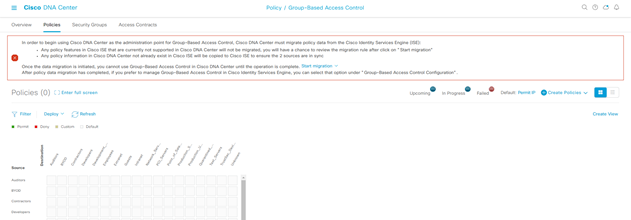
La policy è cosi creata ed inserita in una lista con status Created.
In caso di opzione Bi-Directional, la reverse-policy è anche creata.
Select Deploy (selezionare il simbolo dei quattro quadratini bianchi nel rettangolo celeste)
Step-3: selezionare per la policy il Deploy significa rendere questa applicata in SD-Access Fabric e disponibile in ISE, vista utilizzando Cisco TrustSec policy matrix.
Step-4: collegarsi ad ISE e navigate to Work Centers > TrustSec > TrustSec Policy and then on the left site select Matrix
Verificare la policy matrix TrustSec se è creata correttamente
Segmentation with third-part Radius
In caso di Radius Server non Cisco, è sempre possibile la gestione delle policies SGT integrate tra ISE e DNAC.
Example Flow Scenario:
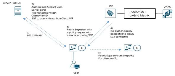
Secure host onboarding è il processo di onboarding di tutti i sistemi in rete includendo workstation, BYOD, IoT, IP phones, VideoCamera, come pure Access-Point.
L’integrazione in rete di questi devices è possibile attraverso meccanismi di sicurezza basati su 802.1x ed ISE assume un ruolo chiave per questo.
802.1x è un sistema port-based authentication che permette in modo sicuro di autenticare o meno un determinato devices che prova a collegarsi in rete attraverso uno switch.
802.1x utilizza differenti modi di configurazione tra cui:
- Single-Host mode: solo un singolo MAC address è permesso ad accedere in rete
- Multi-Host mode: il primo MAC address che si connette in rete è autorizzato; una sequenza di ulteriori hosts che si collegano alla porta, bypass l’autenticazione e si pongono in una condizione chiamata “piggyback” dove poggiano sul primo MAC address autenticato (utilizzato quando si gestisce un numero n. di mac-address collegati ad una specifica porta switches
- Multi-Domain mode: si riferisce a sistemi di tipo data e voice che si connettono in un MDA authentication; i due sistemi sono autorizzati in modo indipendente assegnando ciascuno il valore di vlan-Voice (voice domain) per il phone ed il valore di vlan-Data per l’host (data domain)
- Multi-Auth Mode: come sopra con la differenza che multipli host possono autenticarsi nel dominio data (vlan-Data; è un solo valore di vlan-id). DNAC di default utilizza questa modalità.
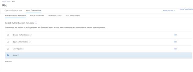
DNAC offre quattro classi di authenticazione:
- Closed Authentication: molto sicuro è basato su 802.1x, il traffico è permesso solo se l’autenticazione è andata a buon fine;
- Open Authentication: moderatamente sicuro
- Low Impact: moderatamente sicuro è basato su LDAP in combinazione con il MAC (Mac Address Bypass)
- None: insicuro, utilizzato per sistemi che non richiedono autenticazione
STEP-1: navigate to Provision > Fabric Site > Site > Authentication Template > Host Onboarding
DNAC Device Discovery
Discovery and Manage Network Devices
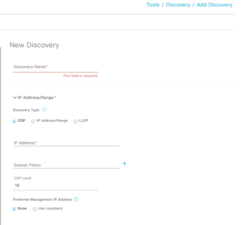
Step-1: navigate to Tools > Discovery > Add Discovery
Enter
- Discovery Name:
- IP Address Range:
- Discovery Type (CDP; IP address/range; LLDP)
- IP Address:
- Subnet Filters:
- CDP Level:
- Preferred Management IP Address (None; Use Loopback):
Step-2: in caso di ulteriori IP ranges, è possibile aggiungerli attraverso il + e ripetere l’operazione.
Step-3: verificare le credenziali utilizzate per il discovery quali CLI e SNMP, impostate per i devices attraverso il DNA-Center ed infine click su Discover.
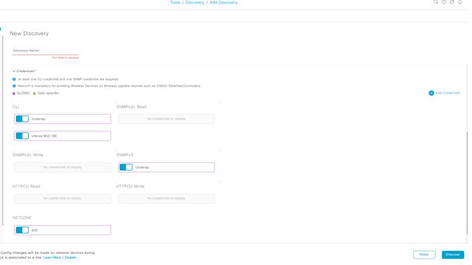
Il Discovery inizia il running operation.
In caso di un qualsiasi discovery failures, è necessario ricontrollare il devices list per risolvere il problema e restartare il discovery per questi devices via qualsiasi add devices to add to the inventory.
Step-4: una volta completato il discovery, navigate to Provision > Inventory > e verificare che i devices scoperti siano presenti nella lista di inventory; ogni devices presenta uno status di Manageability il chè significa che il DNA-Center mantiene una interna copia (mirroring) dell’apparato fisico in questione.
Nota:
Per Catalyst 6800 series switch, Cisco prevede di poter evitare il discovery, inserendo in questi devices il seguente comando, in configuration mode: snmp mib flash cache
In caso il sistema Wireless Lan Controllers non è nella lista Inventory, è possibile aggiungerlo in un secondo momento ripetendo le stesse operazioni previste dallo step precedente, settando il Discovery Name = WLC ed assegnando il range IP Address a loro dedicato.
Best Practices Cisco indicano di utilizzare due WLCs dello stesso tipo e creare un sistema in HA SSO per alta affidabilità e resilienza.
DNAC Device Software Images
Image Repository
Step-1: navigate to Design > Image Repositoty > Family Name
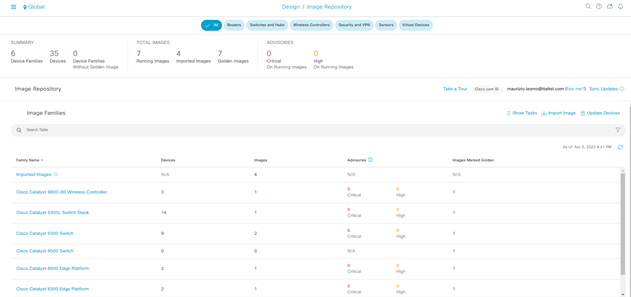
Step-2: click on Family Name la serie di devices da aggiornare
Step-3: select Major Version or Golden Images and then importing and tagging images as golden until all devices are marked with the appropriate version.
- Major Version: list of cisco software release
- Golden Images
- Tagged
- Not Tagged
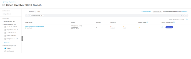
Nota:
in caso di image non ancora importate, è possibile fare un Import Image/Add-on and select Import
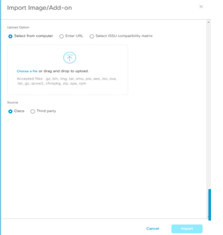
A questo punto l’image è nel repository e disponibile per essere taggata come Golden per i devices
Step-4: Ripetere le operazioni di cui sopra assegnando per ciascuna famiglia di devices Cisco la corretta e consigliata release da Cisco.
Nota:
I devices che non sono compatibili con le release taggate Golden sono marcate come Outdated in Inventory.
L’inventory, quindi, deve essere una lista di devices che hanno acquisito la corretta release software e marcati come Managed.
Update Devices Software
Step-1: navigate to Provision> Inventory > Select the Device Name > Action > Software Image > Image Update
Una volta aggiornata la release software verificare lo status di update
DNAC Provisioning Underlay with LAN-Automation
Questo parte prevede la procedura basata su Lan Automation.
Lan Automation abilita il discovery dei devices compatibili per mezzo di seed devices (il seed devices è lo switch madre dove tutti i nuovi, ed ancora non gestiti, devices si connettono per la loro automatizzazione in SD-Access).
CLI Credential e SNMP sono creati per mezzo di PnP Agent e la rete IP di management utilizzata come strumento di raggiungibilità dei nodi dal sistema DNA.
Le porte di un seed devices collegate ai nodi da discoverare debbono essere layer 2 mode e non debbono appartenere a reti OOB di management.
Di solito un seed devices ha configurato il vtp mode transparent e MTU = 9100.
Affinchè i devices da discoverare debbono lavorare in PnP agent con nessuna pre-configurazione, qualsiasi precedente configurazione fatta deve essere cancellata (restore) allo stato compatibile con il PnP agent e pertanto Cisco prevede la seguente configurazione in config-mode ed exec-mode:
sw(config)# config-register 0x2102
sw(config)# crypto key zeroize
sw(config)# no crypto pki certificate pool
sw# delete /force vlan.dat
sw# delete /force nvram:*.cer
sw# delete /force nvram:pnp*
sw# delete /force flash:pnp*
sw# delete /force stby-nvram:*.cer
sw# delete /force stby-nvram:*.pnp*
! previous two lines only for HA systems
write erase
reload
Nota by Cisco:
Do not save the configurations for the reload process; to prepare switch stacks for LAN Automation, use the same restoration commands for each switch in the stack.
Switch stacking requirements do not change for LAN Automation—all switches in a stack must be running the same software license and version supporting IP routing features.
If you desire the most control over port numbering and stack behavior, then in advance of starting the LAN Automation process, you can adjust the switch stack numbering and also influence a switch to become the ACTIVE role within a stack through an increased priority by using the following commands in exec mode:
sw [switch stack number] renumber [new stack number]
sw [switch stack number] priority 15
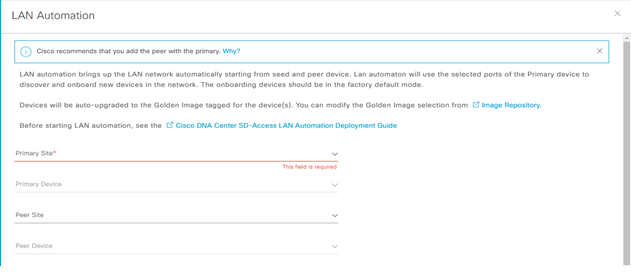
If a golden image has been tagged as described in the previous procedure, image upgrade will occur during LAN Automation if the discovered device is running in INSTALL mode.
If the golden image has been tagged and the discovered device is running in BUNDLE mode, LAN Automation will fail for the device.
Lan-Automation Provision
Identify one or two devices that are in the inventory and managed by Cisco DNA Center to assign to the seed device role at a site. The same seeds can be used for multiple runs of the LAN Automation feature, allowing the discovered devices to be assigned to different buildings or floors for each run.
Identificare uno o più devices in Inventory ed assegnare loro il ruolo di SEED per site; questo stesso seed devices può essere usato per multipli Lan Automation scope, permettendo ai devices rilevati di essere assegnati a differenti building.
Step-1: navigate to Provision > Inventory > select the devices > Action > Provision > Assign Device to Site > Apply
Step-2: navigate to Provision > Inventory > Action > Provision > Lan Automation
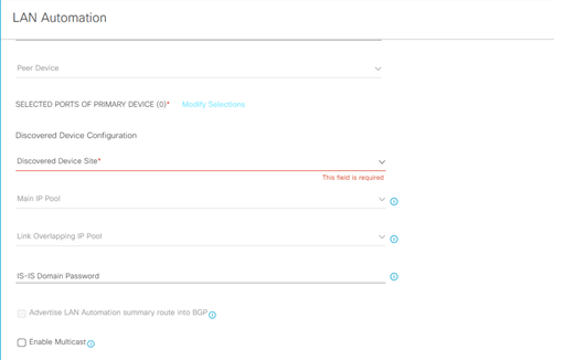
Enter:
- Primary Site:
- Primary Devices:
- Peer Site:
- Peer Devices:
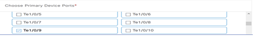
SELECTED PORTS OF PRIMAR DEVICE (0)
Discovered Device Configuration
- Discovered Device Site:
- Main IP Pool: (the main ip pool is used for the devices management IP and DHCP server; it is also used for links and if the a link overlapping IP pool is not provisioned)
- Link Overlapping IP Pool: (provide this pool if you want to use the same IP pool at different site)
- IS-IS Domain Password: (lan automation use this password if it is used by seed devices)
- Advertise Lan Automation summary route into BGP: (if BGP is operational on the primary device and peer devices, then add a summary route for the selected main IP pool into BGP on the primary and peer device)
- Enable Multicast: enable underlay native multicast, configure seed devices as RP and configure discovered devices as subscriber to multicast traffic
Lan-Automation Status
Step-3: navigate to Provision > Inventory > Action > Provision > Lan Automation Status
Verifica Summary
Verifica Devices
Verifica Logs
Nota:
LAN Automation realizza il discovery dei devices attraverso la Vlan di default VLAN1 ed il protocollo ISIS underlay per la raggiungibilità dei devices da scoprire. Quest’ultimi sono inseriti e gestiti nella lista di Inventory.
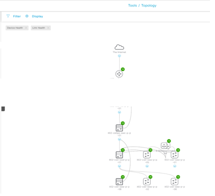
LAN-Automation Topology
Step-1: navigate to Tools > Topology > Global
Step-2: navigate to Tools > Topology > Hierarchy sites
Selezionare ogni singolo site per Verificare la topologia di dettaglio:
Provision Devices Role and Assign Site
Step-1: navigate to Tools > Topology > select each site > select each node > Network Role
Step-2: navigate to Provision > Inventory > select (filter) the devices > Action > Provision > Assign Devices to Site
Enter
Choose a floor
Step-3: click next and skip on Configuration > Advanced Configuration > Summary
- Verifica la configurazione per ciascun devices
- Click Deploy
- Apply
Il Provisioning comincia a lavorare.
Step-3: Ripetere l’operazione per ogni devices che è stato aggiunto; DNA-Center pxGrid integration aggiorna, quindi, i devices in ISE.
Step-4: verificare che i devices sono stati aggiunti ad ISE, andando su ISE to Administration > Network Resources > Network Devices.
Provisioning WLC Integration
Step-1: navigate to Provision > Inventory > select (filter) the WLC > Action > Provision > Configure WLC HA
Nota:
in HA mode, il WLC è visto come una singola entità logica in SD-Access; verifica la configurazione in HA SSO andando a cliccare il device name eppoi High Availability tab.
Step-2: Assign the site e ripetere quindi l’operazione vista in precedenza per questo punto.
Il WLC è assegnato to the site ed il provisioning comincia a lavorare; utilizza il Refresh button sino a che il Provision Status mostra il Success prima di procedere.
DNAC Provisioning Overlay
SD-Access supporta la seguente orchestrazione:
- Fabric Site: significa una Fabric indipendente che include dei Control-Plane Node, Edge Node per le funzionalità di accesso, Border Node per funzionalità di Egress Fabric Site ed infine sistemi quali ISE e WLC fabric mode.
- Transit Site or Network: riferito a collegamenti tra la Fabric ed External Domain (conosciuti come IP-based transit) oppure tra uno o più Fabric Site preservando comunque tra questi le policy di segmentazione (conosciuti come SD-Access transit)
- Fabric Domain: riguarda un unico dominio di amministrazione che abbraccia uno o piu site ed i corrispondenti transit network.
IP-based transit di solito utilizza sistemi con VRF-lite per la connettività verso external networks.
SD-Access transit trasporta SGT (micro-segmentation) e VNs information (macro-segmentation) tra Fabric site, creando di fatto un campus distribuito.
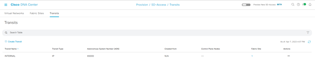
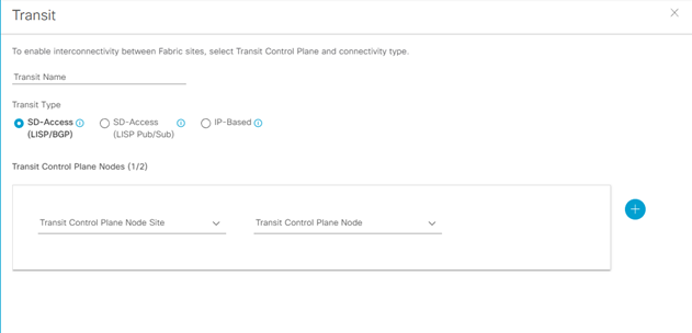
Network Transit
Step-1: navigate to Provision > Transit > Create Transit
Enter
- Transit Name:
- Transit Type (SD-Access LISP/BGP; SD-Access LISP Pub/Sub); IP-Based):
- Transit Control Plane Nodes Sites – Transit Control Plane Node
- Protocol: BGP
- Autonomous System Number:
Fabric Domain, Fabric Site
Step-1: navigate to Provision > Fabric Site > Create Fabric Sites and Fabric Zone
A sinistra del menu la Fabric Enabled Sites hierarchy, selezionata e creata attraverso lo step-1
La Fabric Infrastructure mostra un’architettura a due livelli (access-distribution) oppure a tre livelli (access-distribution-core).
La Host Onboarding evidenzia le seguenti funzionalità:
- Authentication Template
-
- Virtual Networks
-
- Wireless SSIDs
-
- Port Assignment
Fabric Control Plane Node Roles
I nodi con funzionalità di Control Plane Node (senza il ruolo di Border Node), necessitano di essere assegnati come CP (Control Plane).
Per questo è sufficiente selezionare il nodo (hostname), click su esso eppoi nel popup box, click su Add as CP.
Fabric Border Node Roles
I nodi con funzionalità di Border Node hanno necessità di assegnare ad essi differenti funzionalità, quali:
Step-1:
click sul nodo hostname
- Add as Border or Add as CP+Border
Under Layer 3 Handoff
- Select Border
- Supply BGP Local Autonomous Number
Under Select IP Address Pool
- Choose the global IP pool configured previously for border connectivity
For External Border
- Click Is this site connected to Internet?
Transit
- Select the transit
Add button
Step-2:
Click IP Transit text
Click + Add Interface (in the box select the interface for the connection to the fusion router outside Fabric
Below the BGP ASn expand the Virtual Network and select each VN used in the Fabric to include in the Layer 3 Handoff outside the Fabric
Click Save
Click Add
In caso di più Fabric Border Node, ripetere i precedenti due steps.
Dopo che tutti i roles sono stati assegnati, click Save, use the default choise Now, and then click Apply.
Il Fabric Domain è creato.
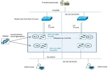
Fabric Layer 2 Border Node Migration Process
Per processi di migrazione tra una architettura ASIS verso SDA Fabric, vengono utilizzati dedicati Fabric Layer 2 Border per semplificare la transizione layer 2 da vlan tradizionali a fabric-enabled vlan.
Questi nodi, difatti, traducono la vlan tradizionale in una fabric-enabled vlan all’interno della Fabric.
|
Example Configuration Fabric Edge Node (VL1024) |
Example Configuration Fabric L2 Border Node (VL300) |
|
instance-id 8188 remote-rloc-probe on-route-change service ethernet eid-table vlan 1024 broadcast-underlay 239.0.0.1 database-mapping mac locator-set xxx exit service-ethernet exit instance-id interface vlan 1024 description mapping vlans1024-300 mac-address 0000.0c9f.f45c vrf forwarding Migration ip address 10.10.10.1 255.255.255.0 ip helper-address 10.100.100.101 no ip redirects ip route-cache same-interface no lisp mobility liveness test lisp mobility 1024_300_MIGRATION |
instance-id 8188 remote-rloc-probe on-route-change service ethernet eid-table vlan 300 broadcast-underlay 239.0.0.1 database-mapping mac locator-set xxx exit service-ethernet exit instance-id interface vlan 300 description mapping vlans1024-300 mac-address 0000.0c9f.f45c vrf forwarding Migration ip address 10.10.10.1 255.255.255.0 ip helper-address 10.100.100.101 no ip redirects ip route-cache same-interface no lisp mobility liveness test lisp mobility 1024_300_MIGRATION |
Nota:
Layer 2 Border Node non supporta configurazioni multihomed; permette solo collegamenti verso switch non-fabric in access mode oppure trunk mode per singolo external devices.
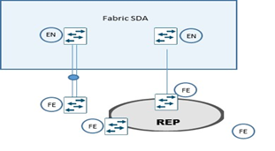
Extended Node
Extended Node sono particolari nodi layer 2 connessi sempre ad un Fabric Edge node, che collegano sistemi quali IoT e/o altri, performano 802.1x oppure MAB authentication.
Asegnazione di vlans sono possibili attraverso ISE, ma un SGT value non può essere assegnato ad un extended node; gli end-user connessi ad un extended node sono comunque gestiti da DNAC attraverso una policy statica VLAN-to-SGT configurata e mappata su un Edge Node, il quale node performa i protocolli LISP (rloc-ied), VXLAN e SGT (scalable group access control).
Un extended node può gestire traffico multicast per la sola ricezione dei pacchetti per receiver ad esso collegati.
La modalità di collegare un extended node alla Fabric SDA sono via un port-channel connesso ad un singolo Fabric Edge.
Il port-channel supporta PAgP (Port Aggregation Protocol).
Un altro metodo è riferito al ring REP (Resilient Ethernet Protocol) molto usato per fast convergence, resiliency and HA.
STEP-1: apply device credential (CLI and SNMP settings) at site level whee the extended node need to be provisioned from DNAC (Design > Network Hierarchy);
STEP-2: add an IP address pool for the extended node management; if the extended node is provisioned via PnP automatically onbording, configure an IP pool for DNAC to assign a loopback interface address for the discovery process;
STEP-3: Reserve an IP pool for the IoT client connected to extented node at fabric site level where the extended node is assigned;
STEP-4: create a VN (virtual network) for pool IoT devices for security reason if required; VN creation is not necessary if the IoT devices will be part of the existing VN as the campus users (SGTs leverage to apply segmentation policies if the IoT devices are in the same VN as campus user);
STEP-5: configure a port-channel on Fabric Edge for th extended node link;
STEP-6: assign the extended node management IP address pool (created in step-2) under Privision > Fabric Sites > Host Onboarding > Virtual Network section and click INFRA_VN
Click Pool Type and choose Extended.
Questa operazione permette l’inserimento dell’extended node come device di infrastruttura e posizionato nella INFRA_VN (simile a quanto succede per gli AP) e risulterà una SVI creata per l’IP pool stesso.
DNAC Enable Multicast
Questa procedura prevede la configurazione del native-multicast:
Assumption:
- SD-Access supporta ASM e SSM
- Sources possono essere all’interno delle VN oppure fuori Fabric
- Rendezvous Point dovrebbero essere configurati a livello di Border Node
- PIM messages sono unicast tra Border ed Edge node
- I pacchetti multicast sono replicati a livello di head-end Border devices verso la parte di Edge nodes.
Step-1: navigate to Design > Network Settings > IP address pool
Create a pool under the global site hierarchy and reserve the pool in the respective site
Un global pool è dedicato per unicast IP loopback interfaces in overlay VN con multicast enabled per la trasmissione di PIM Join
Step-2: navigate to: Provision > Fabric Site > click on Fabric Border Node > select Enable Rendezvous Point.
Step-3: all’interno del match Associate Multicast Pool to VNs, sotto Associate Virtual Networks, scegliere la VN e sotto Select IP Pool, scegliere il pool creato per il Muslticast, click Next eppoi Enable.
Step-4: ripetere i precedenti steps per eventuali altri Fabric Node; click Save eppoi Apply.
DNA-Center prevede la configurazione per il Multicast sui Border Node, crea le loopback con MSDP peering attivo per il Rendezvous Point state communication tra Border Node.
Step-5: in caso di multicast MSDP peering all’esterno rispetto ai Border Node verso il Fusion Router, settare la seguente configurazione per ogni Border Node:
Global level:
ip multicast-routing
ip pim rp address < RP address >
ip pim register-source loopback0
ip pim ssm default
Interface level:
ip pim sparse-mode
Step-6: enable Native Multicast for IPv4 > Save > leave the default selection of Now > click Apply.