mpls LSP on multi-area with different example of areas ospf ed isis e verifica output di funzionamento
04.05 2020 | by massimilianoQuesto documento si prefigge di verificare con una rete di laboratorio “easy” come un LSP-MPLS si comporta rispetto a differenti […]
https://www.ingegnerianetworking.com/wp-content/uploads/2020/05/lsp-normal-area-eb3.png
Questo documento si prefigge di verificare con una rete di laboratorio “easy” come un LSP-MPLS si comporta rispetto a differenti aree OSPF e quali configurazioni e redistribuzione necessitano
Gli esempi seguenti evidenziano le seguenti architetture
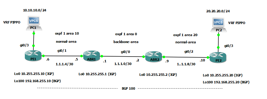
- – rete mpls ldp in un contesto di multi-area ospf costituita da un’area di backbone e due normal-area
- – rete mpls ldp in un contesto di multi-area costituita da un’area di backbone e due aree Stub
- – rete mpls ldp in un contesto di multi-area costituita da un’area di backbone e due totally Stub aree
- – rete mpls ldp in un contesto di multi-level ISIS costituita da un Level-2 (backbone) e due Level-1 (Stub)
1) architettura multi-area OSPF con normal-area
Esempio di configurazione
|
PE1
|
PE2 |
|
ip vrf PIPPO rd 100:100 route-target export 100:100 route-target import 100:100 ! mpls label protocol ldp ! interface Loopback0 description Lo0-IGP ip address 10.255.255.10 255.255.255.255 ip ospf 1 area 0.0.0.10 ! interface Loopback100 description Lo100-BGP ip address 192.168.255.10 255.255.255.255 ip ospf 1 area 0.0.0.10 ! interface GigabitEthernet0/1 description to-ABR1 ip address 1.1.1.6 255.255.255.252 ip ospf 1 area 0.0.0.10 mpls ip ! interface GigabitEthernet0/3 description LAN10 ip vrf forwarding PIPPO ip address 10.10.10.1 255.255.255.0 ! router ospf 1 router-id 10.255.255.10 ! router bgp 100 bgp router-id 192.168.255.10 bgp log-neighbor-changes no bgp default ipv4-unicast neighbor 192.168.255.20 remote-as 100 neighbor 192.168.255.20 update-source Loopback100 ! address-family ipv4 exit-address-family ! address-family vpnv4 neighbor 192.168.255.20 activate neighbor 192.168.255.20 send-community extended exit-address-family ! address-family ipv4 vrf PIPPO redistribute connected exit-address-family |
ip vrf PIPPO rd 100:100 route-target export 100:100 route-target import 100:100 ! mpls label protocol ldp ! interface Loopback0 description lo0-IGP ip address 10.255.255.20 255.255.255.255 ip ospf 1 area 0.0.0.20 ! interface Loopback100 description lo100-BGP ip address 192.168.255.20 255.255.255.255 ip ospf 1 area 0.0.0.20 ! interface GigabitEthernet0/2 description to-ABR2 ip address 1.1.1.10 255.255.255.252 ip ospf 1 area 0.0.0.20 mpls ip ! interface GigabitEthernet0/3 description LAN20 ip vrf forwarding PIPPO ip address 20.20.20.1 255.255.255.0 ! router ospf 1 router-id 10.255.255.20 ! router bgp 100 bgp router-id 192.168.255.20 bgp log-neighbor-changes no bgp default ipv4-unicast neighbor 192.168.255.10 remote-as 100 neighbor 192.168.255.10 update-source Loopback100 ! address-family ipv4 exit-address-family ! address-family vpnv4 neighbor 192.168.255.10 activate neighbor 192.168.255.10 send-community extended exit-address-family ! address-family ipv4 vrf PIPPO redistribute connected exit-address-family |
|
ABR1
|
ABR2 |
|
mpls label protocol ldp ! interface Loopback0 description lo0-IGP ip address 10.255.255.1 255.255.255.255 ip ospf 1 area 0.0.0.0 ! interface GigabitEthernet0/0 description to-ABR2 ip address 1.1.1.1 255.255.255.252 ip ospf 1 area 0.0.0.0 mpls ip ! interface GigabitEthernet0/1 description to-PE1 ip address 1.1.1.5 255.255.255.252 ip ospf 1 area 0.0.0.10 mpls ip ! router ospf 1 router-id 10.255.255.1 ! |
mpls label protocol ldp ! interface Loopback0 description Lo0-IGP ip address 10.255.255.2 255.255.255.255 ip ospf 1 area 0.0.0.0 ! interface GigabitEthernet0/0 description to-ABR1 ip address 1.1.1.2 255.255.255.252 ip ospf 1 area 0.0.0.0 mpls ip ! interface GigabitEthernet0/2 description to-PE2 ip address 1.1.1.9 255.255.255.252 ip ospf 1 area 0.0.0.20 mpls ip ! router ospf 1 router-id 10.255.255.2 ! |
TEST di Raggiungibilità PC1 to PC2 (Direzione del traffico from PE1 to PE2)
PC1> ping 20.20.20.20
84 bytes from 20.20.20.20 icmp_seq=1 ttl=60 time=9.966 ms
84 bytes from 20.20.20.20 icmp_seq=2 ttl=60 time=5.545 ms
84 bytes from 20.20.20.20 icmp_seq=3 ttl=60 time=6.225 ms
^C
PC1> trace 20.20.20.20
trace to 20.20.20.20, 8 hops max, press Ctrl+C to stop
1 10.10.10.1 1.768 ms 1.854 ms 1.380 ms
2 1.1.1.5 5.863 ms 5.714 ms 5.192 ms
3 1.1.1.2 5.191 ms 5.891 ms 5.283 ms
4 20.20.20.1 6.533 ms 6.261 ms 5.071 ms
5 *20.20.20.20 5.333 ms (ICMP type:3, code:3, Destination port unreachable)
PE1#traceroute vrf PIPPO 20.20.20.20
Type escape sequence to abort.
Tracing the route to 20.20.20.20
VRF info: (vrf in name/id, vrf out name/id)
1 1.1.1.5 [MPLS: Labels 20/22 Exp 0] 6 msec 9 msec 6 msec
2 1.1.1.2 [MPLS: Labels 20/22 Exp 0] 7 msec 6 msec 6 msec
3 20.20.20.1 7 msec 8 msec 8 msec
4 *
20.20.20.20 8 msec 6 msec
PE1#show ip bgp vpnv4 vrf PIPPO 20.20.20.20
BGP routing table entry for 100:100:20.20.20.0/24, version 4
Paths: (1 available, best #1, table PIPPO)
Not advertised to any peer
Refresh Epoch 1
Local
192.168.255.20 (metric 4) (via default) from 192.168.255.20 (192.168.255.20)
Origin incomplete, metric 0, localpref 100, valid, internal, best
Extended Community: RT:100:100
mpls labels in/out nolabel/22
rx pathid: 0, tx pathid: 0x0
PE1#show ip route 192.168.255.20
Routing entry for 192.168.255.20/32
Known via “ospf 1”, distance 110, metric 4, type inter area
Last update from 1.1.1.5 on GigabitEthernet0/1, 00:38:21 ago
Routing Descriptor Blocks:
* 1.1.1.5, from 10.255.255.1, 00:38:21 ago, via GigabitEthernet0/1
Route metric is 4, traffic share count is 1
From PE2
PE2#show ip bgp vpnv4 vrf PIPPO 20.20.20.20
BGP routing table entry for 100:100:20.20.20.0/24, version 2
Paths: (1 available, best #1, table PIPPO)
Advertised to update-groups:
1
Refresh Epoch 1
Local
0.0.0.0 (via vrf PIPPO) from 0.0.0.0 (192.168.255.20)
Origin incomplete, metric 0, localpref 100, weight 32768, valid, sourced, best
Extended Community: RT:100:100
mpls labels in/out 22/nolabel(PIPPO)
rx pathid: 0, tx pathid: 0x0
|
Verifica MPLS LDP:
|
Verifica MPLS forwarding table: |
|
PE1#show mpls ldp neighbor Peer LDP Ident: 10.255.255.1:0; Local LDP Ident 10.255.255.10:0 TCP connection: 10.255.255.1.646 – 10.255.255.10.23396 State: Oper; Msgs sent/rcvd: 93/95; Downstream Up time: 01:11:22 LDP discovery sources: GigabitEthernet0/1, Src IP addr: 1.1.1.5 Addresses bound to peer LDP Ident: 1.1.1.1 1.1.1.5 10.255.255.1
ABR1#show mpls ldp neighbor Peer LDP Ident: 10.255.255.10:0; Local LDP Ident 10.255.255.1:0 TCP connection: 10.255.255.10.23396 – 10.255.255.1.646 State: Oper; Msgs sent/rcvd: 97/95; Downstream Up time: 01:12:45 LDP discovery sources: GigabitEthernet0/1, Src IP addr: 1.1.1.6 Addresses bound to peer LDP Ident: 1.1.1.6 10.255.255.10 192.168.255.10
Peer LDP Ident: 10.255.255.2:0; Local LDP Ident 10.255.255.1:0 TCP connection: 10.255.255.2.15569 – 10.255.255.1.646 State: Oper; Msgs sent/rcvd: 85/88; Downstream Up time: 01:05:29 LDP discovery sources: GigabitEthernet0/0, Src IP addr: 1.1.1.2 Addresses bound to peer LDP Ident: 1.1.1.2 10.255.255.2 1.1.1.9
ABR2#show mpls ldp neighbor Peer LDP Ident: 10.255.255.1:0; Local LDP Ident 10.255.255.2:0 TCP connection: 10.255.255.1.646 – 10.255.255.2.15569 State: Oper; Msgs sent/rcvd: 92/89; Downstream Up time: 01:09:16 LDP discovery sources: GigabitEthernet0/0, Src IP addr: 1.1.1.1 Addresses bound to peer LDP Ident: 1.1.1.1 1.1.1.5 10.255.255.1
Peer LDP Ident: 192.168.255.20:0; Local LDP Ident 10.255.255.2:0 TCP connection: 192.168.255.20.53091 – 10.255.255.2.646 State: Oper; Msgs sent/rcvd: 66/67; Downstream Up time: 00:48:09 LDP discovery sources: GigabitEthernet0/2, Src IP addr: 1.1.1.10 Addresses bound to peer LDP Ident: 1.1.1.10 10.255.255.20 192.168.255.20
PE2#show mpls ldp neighbor Peer LDP Ident: 10.255.255.2:0; Local LDP Ident 192.168.255.20:0 TCP connection: 10.255.255.2.646 – 192.168.255.20.53091 State: Oper; Msgs sent/rcvd: 70/69; Downstream Up time: 00:50:08 LDP discovery sources: GigabitEthernet0/2, Src IP addr: 1.1.1.9 Addresses bound to peer LDP Ident: 1.1.1.2 10.255.255.2 1.1.1.9
|
PE1#show mpls forwarding-table
Local Outgoing Prefix Bytes Label Outgoing Next Hop Label Label or Tunnel Id Switched interface 16 Pop Label 10.255.255.1/32 0 Gi0/1 1.1.1.5 17 Pop Label 1.1.1.0/30 0 Gi0/1 1.1.1.5 18 18 10.255.255.2/32 0 Gi0/1 1.1.1.5 19 19 1.1.1.8/30 0 Gi0/1 1.1.1.5 20 20 192.168.255.20/32 0 Gi0/1 1.1.1.5 21 21 10.255.255.20/32 0 Gi0/1 1.1.1.5 22 No Label 10.10.10.0/24[V] 1536 aggregate/PIPPO
ABR1#show mpls forwarding-table
Local Outgoing Prefix Bytes Label Outgoing Next Hop Label Label or Tunnel Id Switched interface 16 Pop Label 192.168.255.10/32 4374 Gi0/1 1.1.1.6 17 Pop Label 10.255.255.10/32 0 Gi0/1 1.1.1.6 18 Pop Label 10.255.255.2/32 0 Gi0/0 1.1.1.2 19 Pop Label 1.1.1.8/30 0 Gi0/0 1.1.1.2 20 20 192.168.255.20/32 3461 Gi0/0 1.1.1.2 21 21 10.255.255.20/32 0 Gi0/0 1.1.1.2
ABR2#show mpls forwarding-table
Local Outgoing Prefix Bytes Label Outgoing Next Hop Label Label or Tunnel Id Switched interface 16 Pop Label 1.1.1.4/30 0 Gi0/0 1.1.1.1 17 Pop Label 10.255.255.1/32 0 Gi0/0 1.1.1.1 18 17 10.255.255.10/32 0 Gi0/0 1.1.1.1 19 16 192.168.255.10/32 5315 Gi0/0 1.1.1.1 20 Pop Label 192.168.255.20/32 4258 Gi0/2 1.1.1.10 21 Pop Label 10.255.255.20/32 0 Gi0/2 1.1.1.10
PE2#show mpls forwarding-table
Local Outgoing Prefix Bytes Label Outgoing Next Hop Label Label or Tunnel Id Switched interface 16 19 192.168.255.10/32 0 Gi0/2 1.1.1.9 17 18 10.255.255.10/32 0 Gi0/2 1.1.1.9 18 Pop Label 10.255.255.2/32 0 Gi0/2 1.1.1.9 19 17 10.255.255.1/32 0 Gi0/2 1.1.1.9 20 16 1.1.1.4/30 0 Gi0/2 1.1.1.9 21 Pop Label 1.1.1.0/30 0 Gi0/2 1.1.1.9 22 No Label 20.20.20.0/24[V] 1416 aggregate/PIPPO |
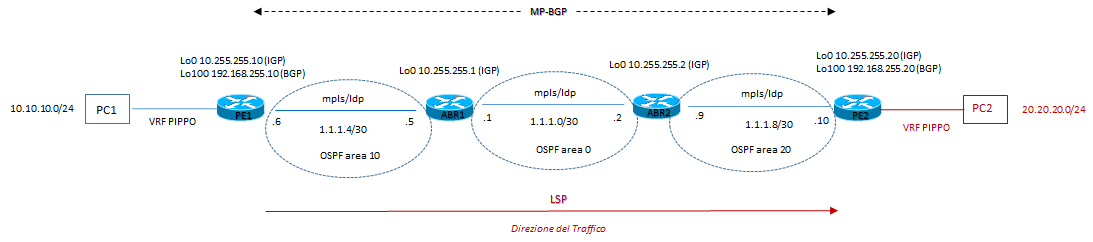
Visione d’insieme grafica:
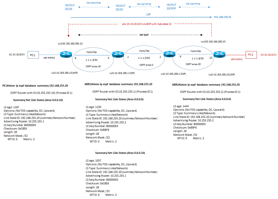
Si ricorda che in una architettura multi-area tra backbone e normal-area abbiamo questa situazione:
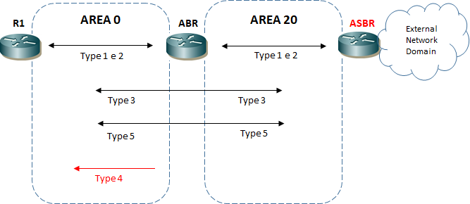
2) architettura multi-area OSPF con STUB-area
Con una STUB area i tipi di LSA che sono permesse sono:
LSA type 1
LSA type 2
LSA type 3 summary
ed inoltre la default-route verso il nodo interno all’area stub
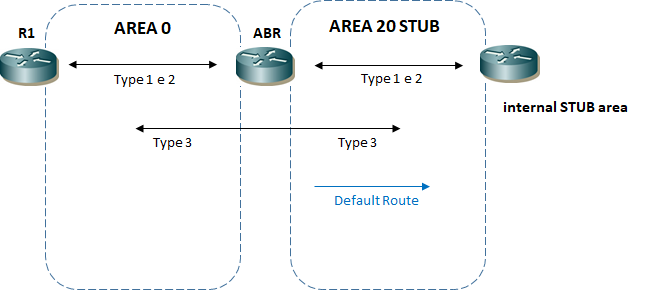
E difatti anche in questo scenario ritroviamo le stesse condizioni medesime viste in precedenza per la condizione di mpls forwarding-table e per il database ospf.
La differenza la troviamo solo a livello di area stub che a differenza di prima riceve anche una default route:
PE1#show ip route
Gateway of last resort is 1.1.1.5 to network 0.0.0.0
O*IA 0.0.0.0/0 [110/2] via 1.1.1.5, 00:10:02, GigabitEthernet0/1
1.0.0.0/8 is variably subnetted, 4 subnets, 2 masks
PE1#show ip bgp vpnv4 vrf PIPPO 20.20.20.20
BGP routing table entry for 100:100:20.20.20.0/24, version 3
Paths: (1 available, best #1, table PIPPO)
Not advertised to any peer
Refresh Epoch 1
Local
192.168.255.20 (metric 4) (via default) from 192.168.255.20 (192.168.255.20)
Origin incomplete, metric 0, localpref 100, valid, internal, best
Extended Community: RT:100:100
mpls labels in/out nolabel/22
rx pathid: 0, tx pathid: 0x0
PE1#show mpls forwarding-table
Local Outgoing Prefix Bytes Label Outgoing Next Hop
Label Label or Tunnel Id Switched interface
16 Pop Label 10.255.255.1/32 0 Gi0/1 1.1.1.5
17 Pop Label 1.1.1.0/30 0 Gi0/1 1.1.1.5
18 18 10.255.255.2/32 0 Gi0/1 1.1.1.5
19 19 1.1.1.8/30 0 Gi0/1 1.1.1.5
20 20 192.168.255.20/32 0 Gi0/1 1.1.1.5
21 21 10.255.255.20/32 0 Gi0/1 1.1.1.5
23 No Label 10.10.10.0/24[V] 0 aggregate/PIPPO
ABR1#show ip ospf database summary 192.168.255.20
OSPF Router with ID (10.255.255.1) (Process ID 1)
Summary Net Link States (Area 0.0.0.0)
LS age: 1222
Options: (No TOS-capability, DC, Upward)
LS Type: Summary Links(Network)
Link State ID: 192.168.255.20 (summary Network Number)
Advertising Router: 10.255.255.2
LS Seq Number: 80000002
Checksum: 0xBAF5
Length: 28
Network Mask: /32
MTID: 0 Metric: 2
Summary Net Link States (Area 0.0.0.10)
LS age: 1678
Options: (No TOS-capability, DC, Upward)
LS Type: Summary Links(Network)
Link State ID: 192.168.255.20 (summary Network Number)
Advertising Router: 10.255.255.1
LS Seq Number: 80000002
Checksum: 0xE8C9
Length: 28
Network Mask: /32
MTID: 0 Metric: 3
PE1#traceroute vrf PIPPO 20.20.20.20
Type escape sequence to abort.
Tracing the route to 20.20.20.20
VRF info: (vrf in name/id, vrf out name/id)
1 1.1.1.5 [MPLS: Labels 20/22 Exp 0] 6 msec 5 msec 5 msec
2 1.1.1.2 [MPLS: Labels 20/22 Exp 0] 6 msec 5 msec 5 msec
3 20.20.20.1 6 msec 6 msec 8 msec
4 20.20.20.20 11 msec 5 msec 6 msec
3) architettura multi-area OSPF con Totally STUB-area
In questo caso ci troviamo in una situazione dove abbiamo questo tipo di LSA permesse:
LSA type 1
LSA type 2
default route
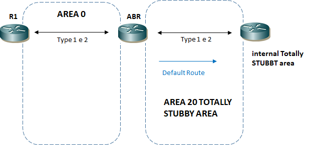
E la situazione per la parte MPLS-LSP cambia.
PE1#traceroute vrf PIPPO 20.20.20.20
Type escape sequence to abort.
Tracing the route to 20.20.20.20
VRF info: (vrf in name/id, vrf out name/id)
1 * * *
2 * * *
3 * * *
4 * * *
PC1> ping 20.20.20.20
20.20.20.20 icmp_seq=1 timeout
20.20.20.20 icmp_seq=2 timeout
20.20.20.20 icmp_seq=3 timeout
20.20.20.20 icmp_seq=4 timeout
20.20.20.20 icmp_seq=5 timeout
PC1> trace 20.20.20.20
trace to 20.20.20.20, 8 hops max, press Ctrl+C to stop
1 10.10.10.1 3.338 ms 2.153 ms 3.234 ms
2 * * *
3 * * *
4 * * *
5 * * *
6 * * *
7 * * *
8 *
PE1#show mpls forwarding-table
Local Outgoing Prefix Bytes Label Outgoing Next Hop
Label Label or Tunnel Id Switched interface
23 No Label 10.10.10.0/24[V] 1536 aggregate/PIPPO
PE1#show ip route
Gateway of last resort is 1.1.1.5 to network 0.0.0.0
O*IA 0.0.0.0/0 [110/2] via 1.1.1.5, 00:12:08, GigabitEthernet0/1
1.0.0.0/8 is variably subnetted, 2 subnets, 2 masks
C 1.1.1.4/30 is directly connected, GigabitEthernet0/1
L 1.1.1.6/32 is directly connected, GigabitEthernet0/1
10.0.0.0/32 is subnetted, 1 subnets
C 10.255.255.10 is directly connected, Loopback0
192.168.255.0/32 is subnetted, 1 subnets
C 192.168.255.10 is directly connected, Loopback100
ABR1#show ip ospf database summary 192.168.255.20
OSPF Router with ID (10.255.255.1) (Process ID 1)
Summary Net Link States (Area 0.0.0.0)
LS age: 719
Options: (No TOS-capability, DC, Upward)
LS Type: Summary Links(Network)
Link State ID: 192.168.255.20 (summary Network Number)
Advertising Router: 10.255.255.2
LS Seq Number: 80000001
Checksum: 0xBCF4
Length: 28
Network Mask: /32
MTID: 0 Metric: 2
Non è presente in area 0.0.0.10
Il path LSP end-to-end si interrompe.
Quindi NON FUNZIONA... ed a questo punto… o quando progettiamo una rete LSP-MPLS lasciamo perdere aree ospf di tipo Totally-Stub oppure….
Questa stessa architettura è paragonabile ad una architettura con ISIS dove abbiamo un Level 2 visto come area backbone e due Level 1 viste come aree differenti (Stub) adiacenti all’area di backbone [ troviamo questa situazione spesso in una architettura di tipo ” seamless mpls ” ]
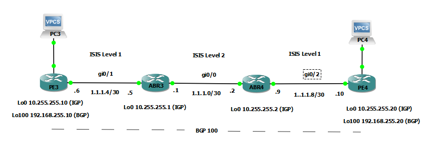
si riportano le configurazioni per maggiori dettagli:
|
PE3 with ISIS
|
PE4 with ISIS |
|
router isis net 49.0001.0000.0000.0010.00 passive-interface default no passive-interface GigabitEthernet0/1 ! interface GigabitEthernet0/1 description to-ABR1 ip address 1.1.1.6 255.255.255.252 ip router isis mpls ip isis circuit-type level-1 isis network point-to-point !
PE3#show isis neighbors Tag null: System Id Type Interface IP Address State Holdtime Circuit Id ABR3 L1 Gi0/1 1.1.1.5 UP 21 00
|
router isis net 49.0001.0000.0000.0020.00 passive-interface default no passive-interface GigabitEthernet0/2 ! interface GigabitEthernet0/2 description to-ABR2 ip address 1.1.1.10 255.255.255.252 ip router isis mpls ip isis circuit-type level-1 isis network point-to-point !
PE4#show isis neighbors Tag null: System Id Type Interface IP Address State Holdtime Circuit Id ABR4 L1 Gi0/2 1.1.1.9 UP 22 01 |
|
ABR3 with ISIS
|
ABR4 with ISIS |
|
router isis net 49.0001.0000.0000.0001.00 passive-interface default no passive-interface GigabitEthernet0/0 no passive-interface GigabitEthernet0/1 ! interface GigabitEthernet0/0 description to-ABR2 ip address 1.1.1.1 255.255.255.252 ip router isis duplex auto speed auto media-type rj45 mpls ip isis circuit-type level-2-only isis network point-to-point ! interface GigabitEthernet0/1 description to-PE1 ip address 1.1.1.5 255.255.255.252 ip router isis duplex auto speed auto media-type rj45 mpls ip isis circuit-type level-1 isis network point-to-point ! ABR3#show isis neighbors System Id Type Interface IP Address State Holdtime Circuit Id ABR4 L2 Gi0/0 1.1.1.2 UP 25 00 PE3 L1 Gi0/1 1.1.1.6 UP 27 00
|
router isis net 49.0001.0000.0000.0002.00 passive-interface default no passive-interface GigabitEthernet0/0 no passive-interface GigabitEthernet0/2 ! interface GigabitEthernet0/0 description to-ABR1 ip address 1.1.1.2 255.255.255.252 ip router isis duplex auto speed auto media-type rj45 mpls ip isis circuit-type level-2-only isis network point-to-point ! interface GigabitEthernet0/2 description to-PE2 ip address 1.1.1.9 255.255.255.252 ip router isis duplex auto speed auto media-type rj45 mpls ip isis circuit-type level-1 isis network point-to-point ! ABR4#show isis neighbors System Id Type Interface IP Address State Holdtime Circuit Id ABR3 L2 Gi0/0 1.1.1.1 UP 27 01 PE4 L1 Gi0/2 1.1.1.10 UP 29 00 |
Vediamo ora di verificare gli output in termini MPLS:
Le adiacenze LDP restano corrette:
PE3#show mpls ldp neighbor
Peer LDP Ident: 10.255.255.1:0; Local LDP Ident 192.168.255.10:0
TCP connection: 10.255.255.1.646 – 192.168.255.10.21182
State: Oper; Msgs sent/rcvd: 58/63; Downstream
Up time: 00:45:17
LDP discovery sources:
GigabitEthernet0/1, Src IP addr: 1.1.1.5
Addresses bound to peer LDP Ident:
1.1.1.1 1.1.1.5 10.255.255.1
ABR3#show mpls ldp neighbor
Peer LDP Ident: 192.168.255.10:0; Local LDP Ident 10.255.255.1:0
TCP connection: 192.168.255.10.21182 – 10.255.255.1.646
State: Oper; Msgs sent/rcvd: 63/58; Downstream
Up time: 00:45:31
LDP discovery sources:
GigabitEthernet0/1, Src IP addr: 1.1.1.6
Addresses bound to peer LDP Ident:
1.1.1.6 10.255.255.10 192.168.255.10
Peer LDP Ident: 10.255.255.2:0; Local LDP Ident 10.255.255.1:0
TCP connection: 10.255.255.2.62961 – 10.255.255.1.646
State: Oper; Msgs sent/rcvd: 59/61; Downstream
Up time: 00:42:22
LDP discovery sources:
GigabitEthernet0/0, Src IP addr: 1.1.1.2
Addresses bound to peer LDP Ident:
1.1.1.2 10.255.255.2 1.1.1.9
ABR4#show mpls ldp neighbor
Peer LDP Ident: 10.255.255.1:0; Local LDP Ident 10.255.255.2:0
TCP connection: 10.255.255.1.646 – 10.255.255.2.62961
State: Oper; Msgs sent/rcvd: 66/64; Downstream
Up time: 00:46:08
LDP discovery sources:
GigabitEthernet0/0, Src IP addr: 1.1.1.1
Addresses bound to peer LDP Ident:
1.1.1.1 1.1.1.5 10.255.255.1
Peer LDP Ident: 192.168.255.20:0; Local LDP Ident 10.255.255.2:0
TCP connection: 192.168.255.20.34969 – 10.255.255.2.646
State: Oper; Msgs sent/rcvd: 61/57; Downstream
Up time: 00:43:19
LDP discovery sources:
GigabitEthernet0/2, Src IP addr: 1.1.1.10
Addresses bound to peer LDP Ident:
1.1.1.10 10.255.255.20 192.168.255.20
PE4#show mpls ldp neighbor
Peer LDP Ident: 10.255.255.2:0; Local LDP Ident 192.168.255.20:0
TCP connection: 10.255.255.2.646 – 192.168.255.20.34969
State: Oper; Msgs sent/rcvd: 58/62; Downstream
Up time: 00:44:18
LDP discovery sources:
GigabitEthernet0/2, Src IP addr: 1.1.1.9
Addresses bound to peer LDP Ident:
1.1.1.2 10.255.255.2 1.1.1.9
Ma le differenze le troviamo nella tabella di forwarding mpls:
| show mpls forwarding table (in situazione normale) | show mpls forwarding table (con totally stub aree/level) |
|
PE1#show mpls forwarding-table
Local Outgoing Prefix Bytes Label Outgoing Next Hop Label Label or Tunnel Id Switched interface 16 Pop Label 10.255.255.1/32 0 Gi0/1 1.1.1.5 17 Pop Label 1.1.1.0/30 0 Gi0/1 1.1.1.5 18 18 10.255.255.2/32 0 Gi0/1 1.1.1.5 19 19 1.1.1.8/30 0 Gi0/1 1.1.1.5 20 20 192.168.255.20/32 0 Gi0/1 1.1.1.5 21 21 10.255.255.20/32 0 Gi0/1 1.1.1.5 22 No Label 10.10.10.0/24[V] 1536 aggregate/PIPPO
ABR1#show mpls forwarding-table
Local Outgoing Prefix Bytes Label Outgoing Next Hop Label Label or Tunnel Id Switched interface 16 Pop Label 192.168.255.10/32 4374 Gi0/1 1.1.1.6 17 Pop Label 10.255.255.10/32 0 Gi0/1 1.1.1.6 18 Pop Label 10.255.255.2/32 0 Gi0/0 1.1.1.2 19 Pop Label 1.1.1.8/30 0 Gi0/0 1.1.1.2 20 20 192.168.255.20/32 3461 Gi0/0 1.1.1.2 21 21 10.255.255.20/32 0 Gi0/0 1.1.1.2
ABR2#show mpls forwarding-table
Local Outgoing Prefix Bytes Label Outgoing Next Hop Label Label or Tunnel Id Switched interface 16 Pop Label 1.1.1.4/30 0 Gi0/0 1.1.1.1 17 Pop Label 10.255.255.1/32 0 Gi0/0 1.1.1.1 18 17 10.255.255.10/32 0 Gi0/0 1.1.1.1 19 16 192.168.255.10/32 5315 Gi0/0 1.1.1.1 20 Pop Label 192.168.255.20/32 4258 Gi0/2 1.1.1.10 21 Pop Label 10.255.255.20/32 0 Gi0/2 1.1.1.10
PE2#show mpls forwarding-table
Local Outgoing Prefix Bytes Label Outgoing Next Hop Label Label or Tunnel Id Switched interface 16 19 192.168.255.10/32 0 Gi0/2 1.1.1.9 17 18 10.255.255.10/32 0 Gi0/2 1.1.1.9 18 Pop Label 10.255.255.2/32 0 Gi0/2 1.1.1.9 19 17 10.255.255.1/32 0 Gi0/2 1.1.1.9 20 16 1.1.1.4/30 0 Gi0/2 1.1.1.9 21 Pop Label 1.1.1.0/30 0 Gi0/2 1.1.1.9 22 No Label 20.20.20.0/24[V] 1416 aggregate/PIPPO |
PE3#show mpls forwarding-table Local Outgoing Prefix Bytes Label Outgoing Next Hop Label Label or Tunnel Id Switched interface 16 No Label 10.10.10.0/24[V] 0 aggregate/PIPPO 17 Pop Label 10.255.255.1/32 0 Gi0/1 1.1.1.5
NOTA: manca l’indirizzo NH 192.168.255.20
ABR3#show mpls forwarding-table Local Outgoing Prefix Bytes Label Outgoing Next Hop Label Label or Tunnel Id Switched interface 16 Pop Label 10.255.255.10/32 0 Gi0/1 1.1.1.6 17 Pop Label 192.168.255.10/32 0 Gi0/1 1.1.1.6 18 Pop Label 10.255.255.2/32 0 Gi0/0 1.1.1.2 19 Pop Label 1.1.1.8/30 0 Gi0/0 1.1.1.2 20 20 10.255.255.20/32 0 Gi0/0 1.1.1.2 21 21 192.168.255.20/32 0 Gi0/0 1.1.1.2
ABR4#show mpls forwarding-table Local Outgoing Prefix Bytes Label Outgoing Next Hop Label Label or Tunnel Id Switched interface 16 Pop Label 1.1.1.4/30 0 Gi0/0 1.1.1.1 17 Pop Label 10.255.255.1/32 0 Gi0/0 1.1.1.1 18 16 10.255.255.10/32 0 Gi0/0 1.1.1.1 19 17 192.168.255.10/32 0 Gi0/0 1.1.1.1 20 Pop Label 10.255.255.20/32 0 Gi0/2 1.1.1.10 21 Pop Label 192.168.255.20/32 0 Gi0/2 1.1.1.10
PE4#show mpls forwarding-table Local Outgoing Prefix Bytes Label Outgoing Next Hop Label Label or Tunnel Id Switched interface 16 No Label 20.20.20.0/24[V] 0 aggregate/PIPPO 17 Pop Label 10.255.255.2/32 0 Gi0/2 1.1.1.9 |
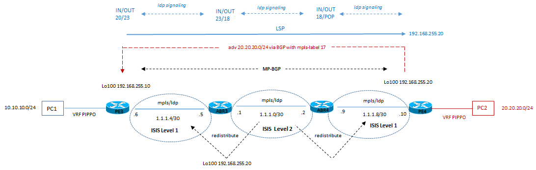
E’ evidente come gli ABR svolgono un ruolo fondamentale per la redistribuzione del corretto Next-Hop (nel nostro caso l’indirizzo 192.168.255.20) per la raggiungibilià della rete target.
La soluzione è quella di permettere una redistribuzione delle loopback operata a livello ABR dal Level-2 to Level-1 secondo questa configurazione:
|
ABR3 with ISIS
|
ABR4 with ISIS |
|
router isis net 49.0001.0000.0000.0001.00 metric-style wide redistribute isis ip level-2 into level-1 route-map L2-L1 passive-interface default no passive-interface GigabitEthernet0/0 no passive-interface GigabitEthernet0/1 ! route-map L2-L1 permit 10 match ip address 10 ! access-list 10 permit 192.168.255.20
|
router isis net 49.0001.0000.0000.0002.00 metric-style wide redistribute isis ip level-2 into level-1 route-map L2-L1 passive-interface default no passive-interface GigabitEthernet0/0 no passive-interface GigabitEthernet0/2 ! route-map L2-L1 permit 10 match ip address 10 ! access-list 10 permit 192.168.255.10 |
A seguito di questa configurazione abbiamo quindi:
PE3#
*May 5 13:59:23.274: %BGP-5-ADJCHANGE: neighbor 192.168.255.20 Up
PE4#
*May 5 13:59:24.848: %BGP-5-ADJCHANGE: neighbor 192.168.255.10 Up
Andiamo a vedere le rispettive tabelle di routing a livello PE (lato interno delle aree/livelli):
PE3#show ip route
Gateway of last resort is not set
1.0.0.0/8 is variably subnetted, 2 subnets, 2 masks
C 1.1.1.4/30 is directly connected, GigabitEthernet0/1
L 1.1.1.6/32 is directly connected, GigabitEthernet0/1
10.0.0.0/32 is subnetted, 2 subnets
i L1 10.255.255.1 [115/10] via 1.1.1.5, 01:04:38, GigabitEthernet0/1
C 10.255.255.10 is directly connected, Loopback0
192.168.255.0/32 is subnetted, 2 subnets
C 192.168.255.10 is directly connected, Loopback100
i ia 192.168.255.20 [115/30] via 1.1.1.5, 00:07:15, GigabitEthernet0/1
PE4#show ip route
Gateway of last resort is not set
1.0.0.0/8 is variably subnetted, 2 subnets, 2 masks
C 1.1.1.8/30 is directly connected, GigabitEthernet0/2
L 1.1.1.10/32 is directly connected, GigabitEthernet0/2
10.0.0.0/32 is subnetted, 2 subnets
i L1 10.255.255.2 [115/10] via 1.1.1.9, 01:05:11, GigabitEthernet0/2
C 10.255.255.20 is directly connected, Loopback0
192.168.255.0/32 is subnetted, 2 subnets
i ia 192.168.255.10 [115/30] via 1.1.1.9, 00:07:33, GigabitEthernet0/2
C 192.168.255.20 is directly connected, Loopback100
Verifichiamo la parte MPLS:
PE3#show mpls forwarding-table
Local Outgoing Prefix Bytes Label Outgoing Next Hop
Label Label or Tunnel Id Switched interface
17 No Label 10.10.10.0/24[V] 0 aggregate/PIPPO
18 Pop Label 10.255.255.1/32 0 Gi0/1 1.1.1.5
20 23 192.168.255.20/32 0 Gi0/1 1.1.1.5
PE4#show mpls forwarding-table
Local Outgoing Prefix Bytes Label Outgoing Next Hop
Label Label or Tunnel Id Switched interface
17 No Label 20.20.20.0/24[V] 0 aggregate/PIPPO
18 Pop Label 10.255.255.2/32 0 Gi0/2 1.1.1.9
20 23 192.168.255.10/32 0 Gi0/2 1.1.1.9
E verifichiamola con il BGP:
PE3#show ip bgp vpnv4 vrf PIPPO 20.20.20.20
BGP routing table entry for 100:100:20.20.20.0/24, version 6
Paths: (1 available, best #1, table PIPPO)
Not advertised to any peer
Refresh Epoch 1
Local
192.168.255.20 (metric 30) (via default) from 192.168.255.20 (192.168.255.20)
Origin incomplete, metric 0, localpref 100, valid, internal, best
Extended Community: RT:100:100
mpls labels in/out nolabel/17
rx pathid: 0, tx pathid: 0x0
PE3#traceroute vrf PIPPO 20.20.20.20
Type escape sequence to abort.
Tracing the route to 20.20.20.20
VRF info: (vrf in name/id, vrf out name/id)
1 1.1.1.5 [MPLS: Labels 23/17 Exp 0] 6 msec 6 msec 7 msec
2 1.1.1.2 [MPLS: Labels 18/17 Exp 0] 5 msec 6 msec 6 msec
3 20.20.20.1 6 msec 5 msec 6 msec
4 20.20.20.20 6 msec 5 msec 5 msec
ABR3#show mpls forwarding-table
Local Outgoing Prefix Bytes Label Outgoing Next Hop
Label Label or Tunnel Id Switched interface
16 Pop Label 10.255.255.10/32 0 Gi0/1 1.1.1.6
17 Pop Label 192.168.255.10/32 9031 Gi0/1 1.1.1.6
18 Pop Label 10.255.255.2/32 0 Gi0/0 1.1.1.2
20 19 10.255.255.20/32 0 Gi0/0 1.1.1.2
21 Pop Label 1.1.1.8/30 0 Gi0/0 1.1.1.2
23 18 192.168.255.20/32 6925 Gi0/0 1.1.1.2
ABR4#show mpls forwarding-table
Local Outgoing Prefix Bytes Label Outgoing Next Hop
Label Label or Tunnel Id Switched interface
16 Pop Label 1.1.1.4/30 0 Gi0/0 1.1.1.1
17 Pop Label 10.255.255.1/32 0 Gi0/0 1.1.1.1
18 Pop Label 192.168.255.20/32 7512 Gi0/2 1.1.1.10
19 Pop Label 10.255.255.20/32 0 Gi0/2 1.1.1.10
22 16 10.255.255.10/32 0 Gi0/0 1.1.1.1
23 17 192.168.255.10/32 9954 Gi0/0 1.1.1.1
Da un punto di vista grafico abbiamo:
PC3> ping 20.20.20.20
84 bytes from 20.20.20.20 icmp_seq=1 ttl=60 time=5.316 ms
84 bytes from 20.20.20.20 icmp_seq=2 ttl=60 time=4.807 ms
84 bytes from 20.20.20.20 icmp_seq=3 ttl=60 time=7.663 ms
^C
PC3>
PC3> trace 20.20.20.20
trace to 20.20.20.20, 8 hops max, press Ctrl+C to stop
1 10.10.10.1 2.452 ms 1.625 ms 1.920 ms
2 1.1.1.5 6.111 ms 5.650 ms 5.077 ms
3 1.1.1.2 8.015 ms 5.944 ms 6.367 ms
4 20.20.20.1 6.111 ms 6.968 ms 7.420 ms
5 * * *
6 *20.20.20.20 6.638 ms (ICMP type:3, code:3, Destination port unreachable)
Ora Funziona.
🙂