SDA cisco: DNA CENTER Design Process (step)
16.02 2024 | by massimilianoDi seguito un elenco ordinato di steps che prevedono la configurazione programmata del DNA Center. Network Design and Discovery PROCEDURE-1: […]
Di seguito un elenco ordinato di steps che prevedono la configurazione programmata del DNA Center.
Network Design and Discovery
PROCEDURE-1: Create Network Site
Step-1: navigate to DESIGN > Network Hierarchy
Step-2: click Add Site > Add Area > Area Name and then click Add
Step-3: click Add Site > Add Building > Building Name, select the site created in step-2 as the Parent and complete the wizard to assign a location, and then click Add
Step-4: Repeat the step-3 as required to adds sites and buildings
Step-5: for integrating wireless to a building or require more granularity for network choises within a building, select the building on the map, choose Add Floor and complete the wizard with own details.
Nota:
Floors sono riferiti durante il wireless provisioning dove gli AP sono assegnati al building floor.
Network Services: AAA – DHCP – DNS
PROCEDURE-2: Configure network services for sites
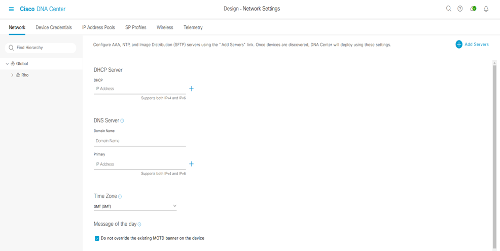
Step-1: navigate to DESIGN > Network Settings > Network > within the left pane in the site hierarchy, select the appropriate level (ex Global), fill the follow details:
- DHCP Server IP address
- DNS Server: Domain Name and IP primary address (and any redundant additional server; it is possible leave the default selection to use Cisco DNA Center for the Syslog and SNMP)
- Save
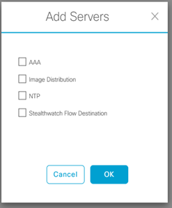
Step-2: click the Add Servers and select the AAA and NTP check boxes and click OK.
Step-3:
- under AAA select the Network and Client/Endpoint check boxes
- under NETWORK select the Server ISE button
- under NETWORK use the pull-down to select the prepolutated ISE server
- under NETWORK select the protocol TACACS button
- under NETWORK select the IP address primary and additional tacacs server
- under CLIENT/ENDPOINT select the Server ISE button
- under CLIENT/ENDPOINT select the protocol RADIUS
- under CLIENT/ENDPOINT select the IP address primary and additional radius server
Step-4: Select the NTP server add the IP address and if you have, also the ip address of additional NTP server, then click save
Device Credential
PROCEDURE-3: Configure device credential for discovery and management
Step-1: navigate to DESIGN > Network Settings > Device Credential > within the left pane in the site hierarchy, select the appropriate level (ex Global), fill the follow details:
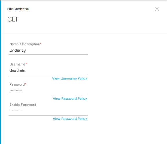
Step-2: select the follow detail on CLI
- Name/Description: Underlay
- Username: dnadmin
- Password: F13r@M1l@n0!
- Enable Password: F13r@M1l@n0!
Save
Nota:
Best Practices Cisco indicano, in caso di utilizzo di ISE come server AAA, di evitare “admin” come username perché causa di eventuale conflitto con il login di ISE, rendendo cosi inagibili i devices stessi.
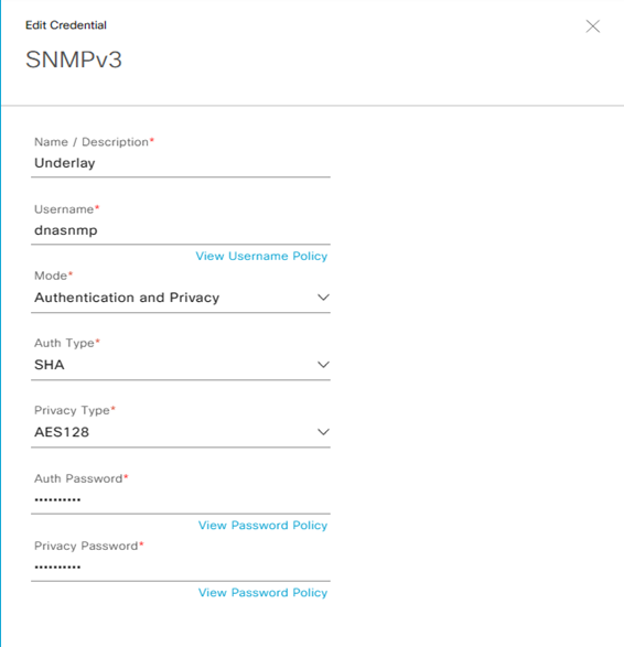
Step-3: select la modalità SNMPv3 and then fill the follow details:
- Name/Description: Underlay
- Username: dnasnmp
- Mode: Authentication and Privacy
- Auth Type: SHA
- Privacy Type: AES128
- Auth Password:
- Privacy Password:
Save
IP Pool Global Address
PROCEDURE-4: Define global IP address Pool
Le opzioni possibili di settare un IP Pool address è manuale attraverso il DNAC oppure inserire gli IP addressess gestiti attraverso un sistema quale IPAM via API.
In questo ultimo caso è necessario navigare dal menu: Design > Network Settings > IP Address Pool > Import > Import from IPAM server
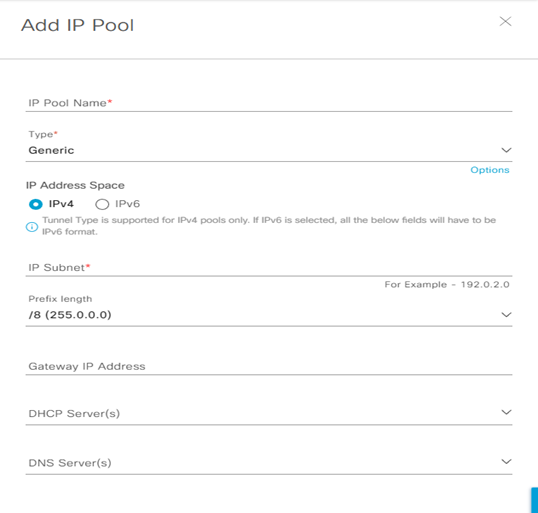
Step-1: navigate to DESIGN > Network Settings > Device IP Address Pool > within the left pane in the site hierarchy, select the appropriate level (ex Global), click the Add button and fill the follow details:
- IP Pool Name:
- Type:
- IP Address Space: set IPv4
- IP Subnet:
- Prefix lenght:
- Gateway IP Address:
- DHCP Server(s):
- DNS Server(s):
Reserve IP Pool address
PROCEDURE-5: Define global IP address Pool to Reserve for site
Step-1: navigate to DESIGN > Network Settings > Device IP Address Pool > Reserve within the left pane in the site hierarchy, select the appropriate level (example Global), click the Add button and fill the follow details:
- IP Pool Name:
- Type:
- IP Address Space:
- IP Subnet:
- Prefix lenght:
- Gateway IP Address:
- DHCP Server(s):
- DNS Server(s):
Step-2: Ripetere le operazioni suddette per ogni nuovo blocco di IP address pool da riservare per ciascun sites.
Fabric Enterprise wireless SSID
PROCEDURE-6: Configure Fabric Enterprise wireless SSID
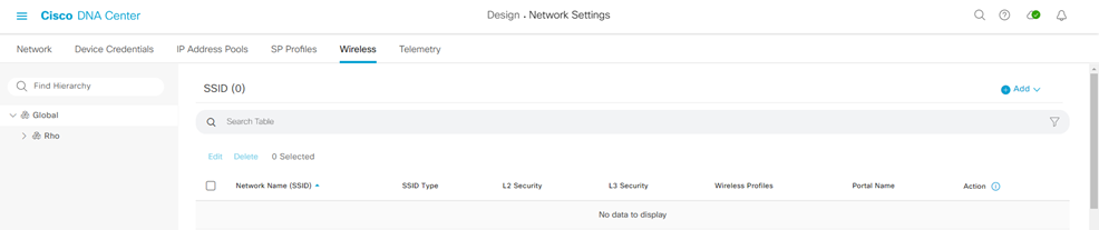
Step-1: navigate to DESIGN > Network Settings > Wireless > within the left pane in the site hierarchy, select the appropriate level (example Global), click the Add button and fill the follow details:
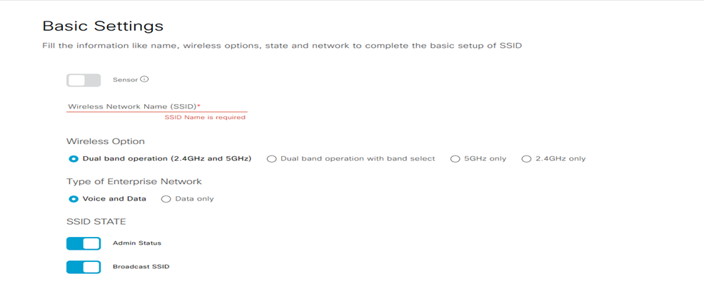
Step-2: create Enterprise wireless network and fill the follow details:
- Wireless Network Name (SSID)
- Wireless Option (dual-band operation; dual-band operation with band select; 5GH only; 2,4 GHZ only):
- Type of Enterprise Network (Voice and Data; Data only):
- SSID State (Admin Status; Broadcast SSID)
Step-3: click next to continue:
- Wireless Profile Name:
- Fabric: YES
- Choose a site: select the location where the SSID broadcast and include floors to include SSID coverage
- SSID State (Admin Status; Broadcast SSID)
Finish
Fabric Guest wireless SSID
PROCEDURE-7: Configure Fabric Guest wireless SSID
Step-1: navigate to DESIGN > Network Settings > Wireless > within the left pane in the site hierarchy, select the appropriate level (ex Global), click the Add button and fill the follow details:
Step-2: create Guest wireless network and fill the follow details:
- Wireless Network Name (SSID)
- Wireless Option (dual-band operation; dual-band operation with band select; 5GH only; 2,4 GHZ only):
- Type of Enterprise Network (Voice and Data; Data only):
- SSID State (Admin Status; Broadcast SSID)
Step-3: click next to continue:
- Wireless Profile Name:
- Fabric: YES
- Choose a site: select the location where the SSID broadcast and include floors to include SSID coverage
- SSID State (Admin Status; Broadcast SSID)
Finish
DNA Center administrative login in ISE
PROCEDURE-8: Create a Cisco DNA Center administrative login in ISE
Step-1: Login in ISE platform and navigate in Administration > Identity Management > Identities > Add
- Name: (matching quello usato per il DNA Center discovery e differente dall’ISE administration)
- Login Password:
- Re-Enter Password:
- Submit
User login è quindi disponibile da ISE e lo stesso user ID è creato per ogni devices discoverato utilizzando Lan Automation
L’integrazione tra ISE e DNAC deve seguire importanti step quali:
- Assicurarsi che le versioni software di entrambi i servizi siano compatibili
Cisco Software-Defined Access Compatibility Matrix
- Enable pxGRID almeno in un nodo ISE deployment; si raccomanda si assegnare un pxGrid Persona in deploymen. pxGrid service in connected status tab ISE web interface;
- DNAC usa ERS API per write and read policy configuration in ISE; pre-requisito ERS (External RESTful Services) deve essere abilitato su ISE. In un deployment distributed ERS write/read necessità di essere abilitato in un nodo PAN per configurazione emantenimento del database (altri nodi debbono avere ERS con read-only permission);
- Assicurarsi che CLI e web interface username e password in ISE abbiano le stesse credenziali; DNAC utilizza le stesse credenziali per il login in CLI e web interface di ISE.
- Assicurarsi che tra il DNAC ed ISE siano aperte le comunicazioni TCP ports 22,443,5222,8910 e 9060.
- Dal punto di vista del DNAC, ISE è integrato come un Authentication and Policy Server
Step-2: Login in DNAC e navigate to System > Settings > Authentication and Policy Server > Add
Enter:
- Server IP address: ip address of ISE PAN deployment (with must interface Gig0)
- Shared Secret: chiave tra network devices e ISE policy server
- Username: username to log in ISE with SSH and GUI
- Password: password to log in ISE with SSH and GUI
- FQDN: fully qualified domain name associated with Gig0 in ISE primary node
- Subscriber Name: usato per identificare il DNAC client name in ISE
- SSH Key (optional):
- Virtual IP address (optional): se ISE policy node dovesse essere dietro Load Balancer
In advanced settings:
- Protocol: enable RADIUS or TACACS
- Authentication Port: port used for Radius Server (default = 1812)
- Accounting Port: port used for Radius Server (default = 1813)
- Port: port used for Tacacs Server (default = 49)