ospf inter-datacenter traffic primario over-backbone and backup over services-provider con verifica redistribuzione prefix ospf IA E1 E2
30.03 2020 | by massimilianoARCHITETTURA DI RIFERIMENTO Obiettivo di questo documento è quello di evidenziare il traffico Inter-DataCenter over backbone (simile […]
https://www.ingegnerianetworking.com/wp-content/uploads/2020/03/ospf-interdc-backbone-e95.png
ARCHITETTURA DI RIFERIMENTO
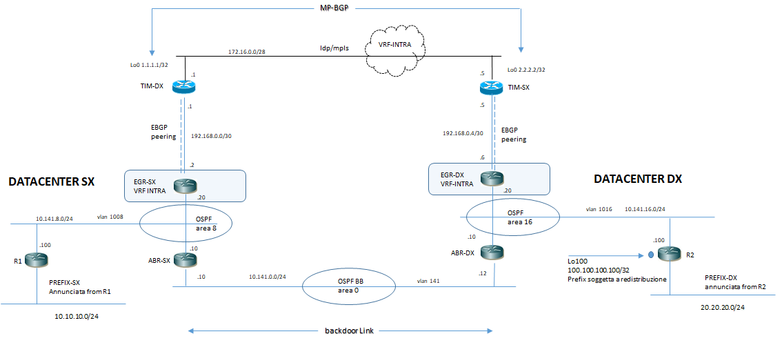
Obiettivo di questo documento è quello di evidenziare il traffico Inter-DataCenter over backbone (simile al concetto di DCI-L3 west-east path) ed in caso di eventuale fault a livello backbone domain utilizzare in modo dinamico un path di backup over service provider via peering EBGP verso i rispettivi POP
Si riportano le configurazioni di LAB
DATACENTER di SX:
| R1 | ABR-SX | EGR-SX |
|
interface GigabitEthernet0/1 description to-backbone no ip address no cdp enable ! interface GigabitEthernet0/1.1008 description to-backbone-ospf8 encapsulation dot1Q 1008 ip address 10.141.8.100 255.255.255.0 ip ospf 1 area 0.0.0.8 no cdp enable ! interface GigabitEthernet0/3 description LAN ip address 10.10.10.1 255.255.255.0 ip ospf 1 area 0.0.0.8 no cdp enable ! router ospf 1 ! |
interface GigabitEthernet0/0 description to-backbone no ip address ! interface GigabitEthernet0/0.141 description to-backbone-area0 encapsulation dot1Q 141 ip address 10.141.0.10 255.255.255.0 ip ospf 1 area 0.0.0.0 ! interface GigabitEthernet0/0.1008 description to-backbone-area8 encapsulation dot1Q 1008 ip address 10.141.8.10 255.255.255.0 ip ospf 1 area 0.0.0.8 ! router ospf 1 |
ip vrf INTRA rd 64512:10 ! interface Loopback0 ip address 3.3.3.3 255.255.255.255 ! interface Loopback1 ip vrf forwarding INTRA ip address 33.33.33.33 255.255.255.255 ! interface GigabitEthernet0/0 description to-SP ip vrf forwarding INTRA ip address 192.168.0.2 255.255.255.252 ! interface GigabitEthernet0/3 description to-backbone no ip address ! interface GigabitEthernet0/3.1008 description to-backbone-ospf8 encapsulation dot1Q 1008 ip vrf forwarding INTRA ip address 10.141.8.20 255.255.255.0 ip ospf 1 area 0.0.0.8 ! router ospf 1 vrf INTRA capability vrf-lite redistribute bgp 64512 subnets ! router bgp 64512 bgp router-id 3.3.3.3 bgp log-neighbor-changes ! address-family ipv4 vrf INTRA bgp router-id 33.33.33.33 redistribute ospf 1 neighbor 192.168.0.1 remote-as 100 neighbor 192.168.0.1 activate neighbor 192.168.0.1 route-map PREP out exit-address-family ! ip prefix-list PRX-DX seq 5 permit 20.20.20.0/24 ! ip prefix-list PRX-SX seq 5 permit 10.10.10.0/24 ! route-map PREP permit 10 match ip address prefix-list PRX-SX ! route-map PREP permit 20 match ip address prefix-list PRX-DX set as-path prepend 64512 ! |
DATACENTER di DX:
| R2 | ABR-DX | EGR-DX |
|
interface Loopback100 ip address 100.100.100.100 255.255.255.255 ! interface GigabitEthernet0/1 description to-backbone no ip address ! interface GigabitEthernet0/1.1016 description to-bb-ospf16 encapsulation dot1Q 1016 ip address 10.141.16.100 255.255.255.0 ip ospf 1 area 0.0.0.16 ! interface GigabitEthernet0/3 description LAN ip address 20.20.20.1 255.255.255.0 ip ospf 1 area 0.0.0.16 ! router ospf 1 redistribute connected metric-type 1 subnets |
interface GigabitEthernet0/0 description to-backbone no ip address duplex auto speed auto media-type rj45 ! interface GigabitEthernet0/0.141 description to-BB encapsulation dot1Q 141 ip address 10.141.0.12 255.255.255.0 ip ospf 1 area 0.0.0.0 ! interface GigabitEthernet0/0.1016 description ospf-16 encapsulation dot1Q 1016 ip address 10.141.16.10 255.255.255.0 ip ospf 1 area 0.0.0.16 ! router ospf 1 |
ip vrf INTRA rd 64513:10 ! interface Loopback0 ip address 4.4.4.4 255.255.255.255 ! interface GigabitEthernet0/0 description to-SP ip vrf forwarding INTRA ip address 192.168.0.6 255.255.255.252 no cdp enable ! interface GigabitEthernet0/3 description backbone no ip address no cdp enable ! interface GigabitEthernet0/3.1016 description to-backbone encapsulation dot1Q 1016 ip vrf forwarding INTRA ip address 10.141.16.20 255.255.255.0 ip ospf 1 area 0.0.0.16 no cdp enable ! router ospf 1 vrf INTRA capability vrf-lite redistribute bgp 64513 subnets ! router bgp 64513 bgp router-id 4.4.4.4 bgp log-neighbor-changes ! address-family ipv4 vrf INTRA redistribute ospf 1 match internal external 1 external 2 neighbor 192.168.0.5 remote-as 100 neighbor 192.168.0.5 activate neighbor 192.168.0.5 route-map PREP out exit-address-family ! ip prefix-list PRX-DX seq 5 permit 20.20.20.0/24 ! ip prefix-list PRX-SX seq 5 permit 10.10.10.0/24 ! route-map PREP permit 10 match ip address prefix-list PRX-DX ! route-map PREP permit 20 match ip address prefix-list PRX-SX set as-path prepend 64513 ! route-map PREP permit 30 ! |
I router di egress hanno il solo compito di CE e mai hanno una funzione attiva di annunci e/o redistribuzione di prefix come invece hanno gli altri devices presenti nelle rispettive aree ospf di competenza; quindi lato router di egress (CE) la ricezione di prefix appartenenti al datacenter opposto via BGP come best-path è normale e corretta.
E’ importante, invece, che i soli router attivi cioà quelli delegati ad annunciare e redistribuire le prefix ricevano le destinazioni con next-hop il router prima appartenente al backdoor link backbone e come “backup” il next-hop del router egress di pertinenza.
Preferred Path selection OSPF:
- Intra-Area (O)
- Inter-Area (O IA)
- External Type 1 (E1)
- NSSA Type 1 (N1)
- External Type 2 (E2)
- NSSA Type 2 (N2)
Verifica OUTPUT:
R1#show ip route
Codes: L – local, C – connected, S – static, R – RIP, M – mobile, B – BGP
D – EIGRP, EX – EIGRP external, O – OSPF, IA – OSPF inter area
N1 – OSPF NSSA external type 1, N2 – OSPF NSSA external type 2
E1 – OSPF external type 1, E2 – OSPF external type 2
i – IS-IS, su – IS-IS summary, L1 – IS-IS level-1, L2 – IS-IS level-2
ia – IS-IS inter area, * – candidate default, U – per-user static route
o – ODR, P – periodic downloaded static route, H – NHRP, l – LISP
a – application route
+ – replicated route, % – next hop override, p – overrides from PfR
Gateway of last resort is not set
10.0.0.0/8 is variably subnetted, 6 subnets, 2 masks
C 10.10.10.0/24 is directly connected, GigabitEthernet0/3
L 10.10.10.1/32 is directly connected, GigabitEthernet0/3
11.0.0.0/32 is subnetted, 1 subnets
20.0.0.0/24 is subnetted, 1 subnets
O IA 20.20.20.0 [110/4] via 10.141.8.10, 02:50:48, GigabitEthernet0/1.1008 # NH via ABR-SX
O E1 100.100.100.100 [110/23] via 10.141.8.10, 02:19:27, GigabitEthernet0/1.1008 # NH via ABR-SX
- La rete 10.10.10.0/24 è direttamente connessa
- La rete 20.20.20.0/24 annunciata direttamente da R2 (DC-SX)) è vista via Inter-Area OSPF from ABR-RZ
- La rete 100.100.100.100/32 redistribuita da R2 (DC-SX) è vista come External Type 1 OSPF from ABR-RZ
Ovviamente il Router R2 ha la seguente configurazione di redistrione in OSPF:
router ospf 1
redistribute connected metric-type 1 subnets
!
R1#show ip ospf database
OSPF Router with ID (10.141.8.100) (Process ID 1)
Router Link States (Area 0.0.0.8)
Link ID ADV Router Age Seq# Checksum Link count
10.141.0.10 10.141.0.10 648 0x8000000E 0x0035FE 1
10.141.8.20 10.141.8.20 615 0x80000010 0x008F73 1
10.141.8.100 10.141.8.100 449 0x8000000F 0x00BD28 2
Net Link States (Area 0.0.0.8)
Link ID ADV Router Age Seq# Checksum
10.141.8.100 10.141.8.100 944 0x80000011 0x00AA1A
Summary Net Link States (Area 0.0.0.8)
Link ID ADV Router Age Seq# Checksum
10.141.0.0 10.141.0.10 648 0x8000000D 0x0053A3
10.141.16.0 10.141.0.10 648 0x80000006 0x00BA32
20.20.20.0 10.141.0.10 648 0x80000006 0x00C78F # ADV Router = ABR-SX
Summary ASB Link States (Area 0.0.0.8)
Link ID ADV Router Age Seq# Checksum
10.141.16.20 10.141.0.10 648 0x80000006 0x00E3F3
10.141.16.100 10.141.0.10 1424 0x80000005 0x00C2C5
Type-5 AS External Link States
Link ID ADV Router Age Seq# Checksum Tag
10.10.10.0 10.141.16.20 1678 0x80000007 0x001FE5 3489725441 # ADV Router = EGR-DX
11.11.11.11 10.141.8.20 1890 0x80000007 0x00B24D 3489725440
11.11.11.11 10.141.16.20 1678 0x80000009 0x00886C 3489725441
20.20.20.0 10.141.16.20 554 0x80000001 0x00C12B 3489725441 # ADV Router = EGR-DX
22.22.22.22 10.141.8.20 1890 0x80000007 0x00B61D 3489725440
22.22.22.22 10.141.16.20 921 0x80000009 0x008C3C 3489725441
100.100.100.100 10.141.8.20 540 0x80000001 0x00B0EF 3489725440 # ADV Router = EGR-SX
100.100.100.100 10.141.16.100 655 0x80000006 0x00BEBF 0 # ADV Router = R2
192.168.0.0 10.141.16.20 1678 0x80000009 0x00C0F9 3489725441
192.168.0.4 10.141.8.20 615 0x80000009 0x00BE01 3489725440
R1#
Il traffico inter-DC primario è rappresentanto in figura:
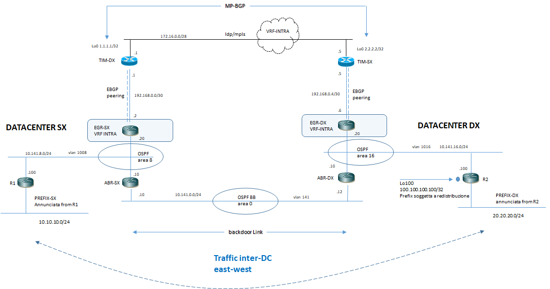
EGR-SX#show ip route vrf INTRA
Routing Table: INTRA
Codes: L – local, C – connected, S – static, R – RIP, M – mobile, B – BGP
D – EIGRP, EX – EIGRP external, O – OSPF, IA – OSPF inter area
N1 – OSPF NSSA external type 1, N2 – OSPF NSSA external type 2
E1 – OSPF external type 1, E2 – OSPF external type 2
i – IS-IS, su – IS-IS summary, L1 – IS-IS level-1, L2 – IS-IS level-2
ia – IS-IS inter area, * – candidate default, U – per-user static route
o – ODR, P – periodic downloaded static route, H – NHRP, l – LISP
a – application route
+ – replicated route, % – next hop override, p – overrides from PfR
Gateway of last resort is not set
10.0.0.0/8 is variably subnetted, 5 subnets, 2 masks
O 10.10.10.0/24
[110/2] via 10.141.8.100, 03:42:01, GigabitEthernet0/3.1008
20.0.0.0/24 is subnetted, 1 subnets
B 20.20.20.0 [20/0] via 192.168.0.1, 00:20:43
22.0.0.0/32 is subnetted, 1 subnets
100.0.0.0/32 is subnetted, 1 subnets
B 100.100.100.100 [20/0] via 192.168.0.1, 00:45:49
EGR-SX#
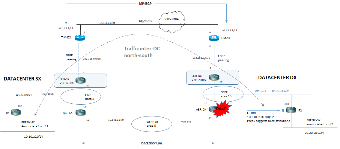
In caso di FAULT from DataCenter di SX
Nel Test spegniamo il router ABR-DX:
R1#show ip route
Codes: L – local, C – connected, S – static, R – RIP, M – mobile, B – BGP
D – EIGRP, EX – EIGRP external, O – OSPF, IA – OSPF inter area
N1 – OSPF NSSA external type 1, N2 – OSPF NSSA external type 2
E1 – OSPF external type 1, E2 – OSPF external type 2
i – IS-IS, su – IS-IS summary, L1 – IS-IS level-1, L2 – IS-IS level-2
ia – IS-IS inter area, * – candidate default, U – per-user static route
o – ODR, P – periodic downloaded static route, H – NHRP, l – LISP
a – application route
+ – replicated route, % – next hop override, p – overrides from PfR
Gateway of last resort is not set
10.0.0.0/8 is variably subnetted, 6 subnets, 2 masks
C 10.10.10.0/24 is directly connected, GigabitEthernet0/3
L 10.10.10.1/32 is directly connected, GigabitEthernet0/3
O E2 20.20.20.0 [110/1] via 10.141.8.20, 00:00:23, GigabitEthernet0/1.1008 # NH via EGR-SX
O E2 100.100.100.100 [110/1] via 10.141.8.20, 00:00:23, GigabitEthernet0/1.1008 # NH via EGR-SX
R1#show ip ospf database external 100.100.100.100
OSPF Router with ID (10.141.8.100) (Process ID 1)
Type-5 AS External Link States
LS age: 425
Options: (No TOS-capability, DC, Upward)
LS Type: AS External Link
Link State ID: 100.100.100.100 (External Network Number )
Advertising Router: 10.141.8.20 # ADV Router = EGR-SX
LS Seq Number: 80000002
Checksum: 0xAEF0
Length: 36
Network Mask: /32
Metric Type: 2 (Larger than any link state path)
MTID: 0
Metric: 1
Forward Address: 0.0.0.0
External Route Tag: 3489725440
LS age: 2470
Options: (No TOS-capability, DC, Upward)
LS Type: AS External Link
Link State ID: 100.100.100.100 (External Network Number )
Advertising Router: 10.141.16.100 # ADV Router = R2
LS Seq Number: 80000006
Checksum: 0xBEBF
Length: 36
Network Mask: /32
Metric Type: 1 (Comparable directly to link state metric)
MTID: 0
Metric: 20
Forward Address: 0.0.0.0
External Route Tag: 0
R1#
Il traffico inter-DC di backup è rappresentanto in figura:
Questo semplice esempio ci fa ricordare un’altro tipo di architettura DataCenter multisite:

Dove R1 ed R2 sono i nostri Leaf mentre i router di Egress sono i nostri Spine