ACI: progetto Multisite best-practices and Nexus Dashboard Orchestrator deploy steps
20.02 2024 | by massimilianoArchitettura di riferimento Best Practices per l’architettura di tipo B2B INTERSITE 3. Solo due Fabric site sono permessi essere collegati […]
Architettura di riferimento
Best Practices per l’architettura di tipo B2B INTERSITE
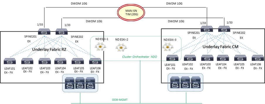
- Collegare i due link DWDM 10G ai rispettivi Spine ACI Fabric
- MACsec encryption abilitato per un traffico sicuro intersite (requisito non essenziale e non configurato ad esempio in ambienti DWDM)
- il rilascio di applicazioni tra differenti datacenter necessità una comunicazione di tipo sicura, privata ed affidabile;
- questo è possibile attraverso l’abilitazione di network-based soluzion quali IPSEC o MACsec;
- ACI release 4.0(1) introduce il supporto di security chiamata “CloudSec” ottenuto attraverso una sorta di multi-hop MACsec permettendo traffico criptato tra due VTEP devices separati da una rete IP.
3. Solo due Fabric site sono permessi essere collegati (impossibilità di forwarding VXLAN-encapsulated da parte degli spine tra differenti site); la soluzione hybrid è consentita ma fuori scope da questo progetto.
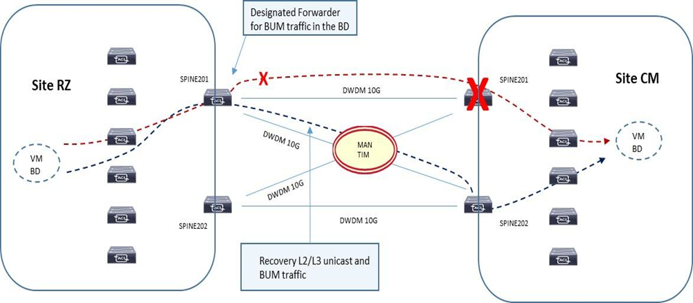
4. L’architettura a quadrato (square) è permessa considerando comunque una configurazione full-mesh BGP tra Spine; da considerare comunque che per il traffico BUM inter-site, questi è sempre originato da uno specifico Spine eletto come come designated-forwarder per un determinato Bridge Domain e destinato verso il O-MTEP (Overlay Multicast) address. Il ricevente Spine ritrasmetterà poi il traffico BUM internamente al suo site (non vi è elezione designated-forwarder lato site ricevente).
5. Per quanto indicato al punto 4 le best-practices indicano una tipologia di collegamento fisico di tipo full-mesh tra gli Spine delle due Fabric ACI e questo per evitare scenari di faults; per il traffico layer-2 e layer-3 unicast semplicemente un recovery fault è garantito per mezzo di un ricalcolo su base VXLAN per i link disponibili su ogni Spine locale, e per il traffico BUM la stessa considerazione è applicata.
6. Gli Spine inter-site debbono essere direttamente collegati fisicamente o logicamente e questo significa che una infrastruttura di tipo layer 2 non è consentita ed il solo impiego di link dark-fiber o DWDM è consentito;
7. L’utilizzo di EoMPLS pseudowire è possibile in modo da rendere compatibile una soluzione P2P tra gli Spine attraverso una rete MPLS core network;
8. Il solo collegamento possibile L3-out back-to-back è di tipo “infra-tenant” con la configurazione via MSO applicata ai rispettivi cluster APIC per un corretto forwarding in termini di VNI, Class-ID translation su Spine inter-site.
9. Almeno uno Spine con soluzione b2b inter-site deve avere un link attivo con LLDP (leaf-facing link)
NOTA: Una funzionalità chiamata “Namespase Normalisation“ prevede un piano di fordwarding Multi-Site attraverso determinati field definiti in VNID, Class-ID associati ad un specifico tenant packet
- Mantenimento separato di name spaces con ID tradotto a livello di Spine Nodes
- È richiesto un hardware dedicato agli Spine per supportare questa funzionalità
- MSO/NDO istruisce gli APIC cluster per programmare la traduzione nelle tabelle di forwarding degli Spine
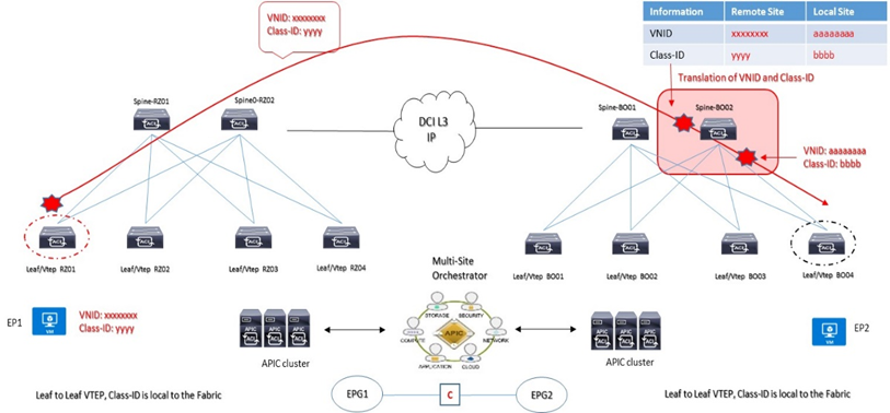
VXLAN VNID = Network information carried across Fabrics (availability zones): identifica un Bridge Domain per comunicazioni layer 2 oppure VRF forwarding per comunicazioni layer 3 di un endpoint oppure un insieme di endpoint sorgenti di traffico
Class-ID = Identity information carried across Fabrics (availability zones): questo valore identifica un gruppo EPG sorgenti di traffico ed hanno significato locale solo all’interno della propria Fabric di competenza.
B2B INTERSITE SETUP
Il sistema MSO è requisito per la configurazione delle policies inter-site eppoi essere applicate ai rispettivi cluster APIC.
- Un L3-out interface deve essere definito come infra-tenant specificando gli Spine nodes e le interfacce coinvolte per la soluzione B2B;
- Un internal TEP pool deve essere definito ed assegnato per il remote site;
- Un external TEP pool deve essere definito ed assegnato ad ogni site; questo external pool provvede per il forwarding data-plane TEP IP impiegato per il MP-BGP EVPN inter-site. Questo stesso pool è utilizzato per assegnare un anycast TEP per ogni site.
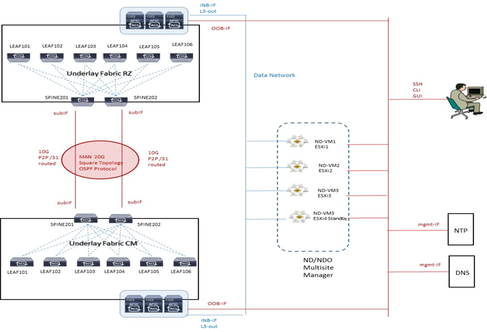
A livello di DWDM le due Fabric vengono collegate attraverso due link 10G come evidenziato nel diagramma seguente:
- Configure day-0 infra-policies
- Select spines establishing MP-BGP EVPN peering with remote sites
- Site Overlay Unicast and Multicast TEP (O-UTEP and O-MTEP)
- Spine MP-BGP EVPN Router-ID (EVPN-RID)
OSPF è utilizzato per la raggiungibilità dei nodi spine con lo scambio di indirizzi TEP ed utilizza sub-interface con vlan-tag 4 verso i rispettivi Spine.
MTU value
Data Plane MTU: l’MTU generato da endpoint (server, router, service node, etc..) collegati ai Leaf node necessita un overhead di 50/54 Bytes di VXLAN encapsulation per inter-site communication
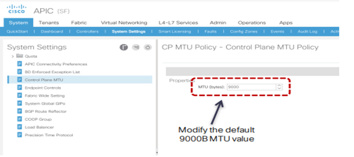
Control Plane MTU: per traffico quale EVPN inter-site si necessità di un valore di default pari a 9000B; il tuning può essere fatto su base “CP MTU Policy” attraverso APIC
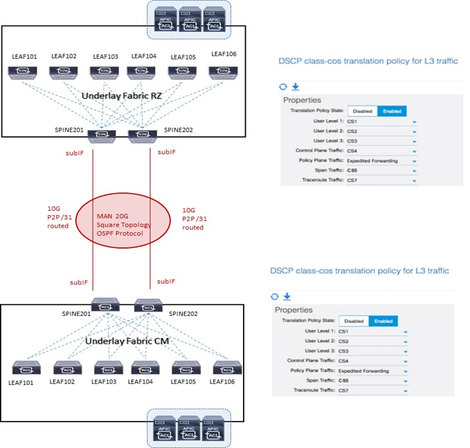
QoS value
ACI Fabric supporta sei classi di servizio ed il traffico è classificato solo a livello ingress-leaf.
Ogni classe è configurata a livello Fabric e mappata in una coda hardware.
| Class of Services (QoS Group) | Traffic Type | Dot1P marking in VXLAN header |
| 0 | Level-3 user data | 0 |
| 1 | Level-2 user data | 1 |
| 2 | Level-1 user-data | 2 |
| 3 | APIC controller traffic | 3 |
| 4 | SPAN traffic | 4 |
| 5 | Control traffic | 5 |
| 5 | Traceroute | 6 |
Il traffico inter-site deve essere settato in modo consistente come succede in modo intra-site e per arrivare a questo obiettivo viene richiesto di configurare un mapping DSCP-to-CoS sui nodi Spine
MP-BGP INTERSITE PEERS
Gli Spine hanno la funzione di stabilire sessioni MP-BGP EVPN tra loro con un dedicato control-plane addressing configurato si ciascun Spine coinvolto.
A livello data plane inter-site due tipologie di traffico sono configurate:
- Anycast Overlay Unicast TEP (O-UTEP) address è assegnato agli Spine tra loro connessi per ricevere L2/L3 traffic unicast;
- Anycast Overlay Multicast TEP (O-MTEP) address è assegnato agli Spine tra loro connessi per ricevere L2 BUM traffic.
Questo piano di indirizzamento è configurabile via NDO orchestrator e deve essere ruotabile via ISN.
MP-BGP EVPN è il protocollo con il quale ciascun endpoint è in grado di comunicare e scambiare informazioni con altri endpoint inter-site; è supportato sia la versione IBGP che EBGP.
Remote host route entries (EVPN type-2) sono associate ad un remote site Anycast O-UTEP address e vi è uno scambio di host-routes solo in presenza di un contratto tra EPG.
NDO ONBOARDING PARAMETER SETTING
| Parameter | Site 1 | Site 2 | Configuration On |
| Site Name | Data Center 1 | Data Center 2 | NDO |
| Site ID | 1 | 2 | NDO |
| BGP AS | < as_dc1 > | < as_dc2 > | NDO |
| BGP peering type | Full-Mesh | Full-Mesh | NDO |
| EVPN-RID Spine 201 (CP-ETEP) | 10.1.1.1/32 | 10.2.2.1/32 | NDO |
| EVPN-RID Spine 202 (CP-ETEP) | 10.1.1.3/32 | 10.2.2.3/32 | NDO |
| O-UTEP (overlay unicast) | 10.1.1.5/32 | 10.2.2.5/32 | NDO |
| O-MTEP (overlay multicast bum) | 10.1.1.7/32 | 10.2.2.7/32 | NDO |
| OSPF area id | 0.0.0.0 | 0.0.0.0 | NDO |
| OSPF interface type | P2P | P2P | NDO |
| External TEP Pool (per Intersite L3Out) | 10.1.1.128/25 | 10.2.2.128/25 | NDO |
| Primo Link DWDM IP Address | 10.1.0.0/31 | 10.1.0.1/31 | NDO |
| Secondo Link DWDM IP Address | 10.1.0.2/31 | 10.1.0.3/31 | NDO |
NOTA:
Control-Plane BGP: mantenere i valori di keepalive-interval (sec), hold-interval (sec), stale-interval (sec) di default e Graceful-Helper enable.
MSO/NDO Features
Le principali funzioni del sistema MSO/NDO sono:
- Gestione di regole di accesso attraverso RBAC (Role Based Access Control);
- L’aggiunta, la cancellazione e la modifica di ACI sites;
- L’impiego della dashboard per la verifica dello stato in termini di health, fault e logs per tutte le inter-site policies che sono parte del dominio ACI Fabric;
- Provisionig day-0 che permette il collegamento ed il peering tra Spine dei due site datacenter; questa capacità prevede l’abilitazione del protocollo MP-BGP control-plane e lo scambio di informazioni host-endpoint (MAC + IPv4 addresses)
- Creazione di Tenant con il rilascio di questi nei due site datacenter;
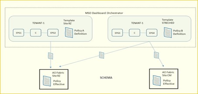
- Definizione di policies template ed associazione di esse ai due site datacenter; le best-practices Cisco raccomandano di gestire tutte le configurazioni per tutti i tenant (object EPG, BD, VRF, Contract) direttamente dal sistema MSO indipendentemente dal fatto che questi oggetti siano streched lungo i due site oppure specifici per un determinato site.
NOTA:
la definizione di “Container” è indicata per uno o più policies-template raggruppati insieme e parte di uno schema; l’associazione di policies di un determinato tenant è comunque sempre definito a livello tenant, non schema.
È necessario per il supporto tra MSO ed ACI una compatibilità tra le rispettive versioni in relazione ai cluster APIC; una connessione “websocket” è impiegata tra il sistema MSO ed ogni APIC registrato in MSO la cui funzione è quella di essere sempre a conoscenza attraverso specifiche query da parte del MSO quando un APIC va in down e poi torna up (caso ad esempio di un APIC upgrade).
NEXUS DASHBOARD ORCHESTRATOR DAY-0 SETUP
La parte Infra Configuration evidenzia un overview dei site da gestire contenente le seguenti informazioni:
- General Settings riguardo il protocollo BGP peering e relativa configurazione;
- On-Premises evidenzia informazioni dei site facenti parte della topologia multisite domain con i numeri di Pods e Spine switches, OSPF settings e Overlay IPs;
STEP-1:
Log in to the Cisco Nexus Dashboard Orchestrator GUI.
STEP-2:
In the left navigation menu, select Infrastructure > Infra Configuration;
In the main pane, click Configure Infra;
In the left sidebar, select General Settings.
STEP-3:
Provide Control Plane Configuration.
- Select the Control Plane Configuration tab.
- Choose BGP Peering Type:
Full-Mesh—All border gateway switches in each site will establish peer connectivity with remote sites’ border gateway switches.
route-reflector—The route-reflector option allows you to specify one or more control-plane nodes to which each site establishes MP-BGP EVPN sessions.- The use of route-reflector nodes avoids creating MP-BGP EVPN full mesh adjacencies between all the sites managed by NDO (non riferito al nostro progetto ma riportato qui per completezza di informazione tecnica)
For ACI fabrics, the route-reflector option is effective only for fabrics that are part of the same BGP ASN.
- In the Keepalive Interval (Seconds) field, enter the keep alive interval seconds.
We recommend keeping the default value.
- In the Hold Interval (Seconds) field, enter the hold interval seconds.
We recommend keeping the default value.
- In the Stale Interval (Seconds) field, enter stale interval seconds.
We recommend keeping the default value.
- Choose whether you want to turn on the Graceful Helper option.
- Provide the Maximum AS Limit.
We recommend keeping the default value.
- Provide the BGP TTL Between Peers.
We recommend keeping the default value.
- Provide the OSPF Area ID.
If you do not have any Cloud APIC sites, this field will not be present in the UI.
This is OSPF area ID used by cloud sites for on-premises IPN peering, which you previously configured in the Cloud APIC for inter-site connectivity in earlier Nexus Dashboard Orchestrator releases.
STEP-4:
Provide the IPN Devices information.
If you do not plan to configure inter-site connectivity between on-premises and cloud sites, you can skip this step.
When you configure inter-site underlay connectivity between on-premises and cloud sites as described in later sections, you will need to select an on-premises IPN device which will establish connectivity to the cloud CSRs. These IPN devices must first be defined here before they are available in the on-premises site configuration screen, which is described in more detail in Configuring Infra: On-Premises Site Settings.
Select the IPN Devices tab.
- Click Add IPN Device.
- Provide the Name and the IP Address of the IPN device.
The IP address you provide will be used as the tunnel peer address from the Cloud APIC’s CSRs, not the IPN device’s management IP address.
- Click the check mark icon to save the device information.
- Repeat this step for any additional IPN devices you want to add.
STEP-5:
In the left navigation menu, select Infrastructure > Infra Configuration;
In the main pane, click Configure Infra;
In the left pane, under Sites, select a specific on-premises site.
STEP-6:
Provide the Overlay Configuration.
- In the right <Site> Settings pane, select the Overlay Configuration tab.
- In the right <Site> Settings pane, enable the Multi-Site knob.
This defines whether the overlay connectivity is established between this site and other sites.
- (Optional) Enable the CloudSec Encryption knob encryption for the site.
CloudSec Encryption provides inter-site traffic encryption. The “Infrastructure Management” chapter in the Cisco Multi-Site Configuration Guide covers this feature in detail.
- Specify the Overlay Multicast TEP.
This address is used for the inter-site L2 BUM and L3 multicast traffic. This IP address is deployed on all spine switches that are part of the same fabric, regardless of whether it is a single pod or Multi-Pod fabric.
This address should not be taken from the address space of the original fabric’s Infra TEP pool or from the 0.x.x.x range.
- (Optional) From the External Routed Domain dropdown, select the domain you want to use.
Choose an external router domain that you have created in the Cisco APIC GUI. For more information, see the Cisco APIC Layer 3 Networking Configuration Guide specific to your APIC release.
- Specify the BGP Autonomous System Number.
- (Optional) Specify the BGP Password.
STEP-7:
Provide the Underlay Configuration.
The following settings are required if you are using OSPF protocol for underlay connectivity between the site and the IPN. If you plan to use BGP instead, you can skip this step. BGP underlay configuration is done at the port level, as described in Configuring Infra: Spine Switches.
- In the right <Site> Settings pane, select the Underlay Configuration tab.
- Provide the OSPF Area ID.
- Select the OSPF Area Type from the dropdown menu.
The OSPF area type can be one of the following:
nssaregular
- Configure OSPF policies for the site.
You can either click an existing policy (for example, msc-ospf-policy-default ) to modify it or click +Add Policy to add a new OSPF policy. Then in the Add/Update Policy window, specify the following:
- In the Policy Name field, enter the policy name.
- In the Network Type field, choose either
broadcast,point-to-point, orunspecified.
- In the Network Type field, choose either
The default is broadcast.
- In the Priority field, enter the priority number.
The default is 1.
- In the Cost of Interface field, enter the cost of interface.
The default is 0.
- From the Interface Controls dropdown menu, choose one of the following:
- advertise-subnet
- bfd
- mtu-ignore
- passive-participation
- In the Hello Interval (Seconds) field, enter the hello interval in seconds.
The default is 10.
- In the Dead Interval (Seconds) field, enter the dead interval in seconds.
The default is 40.
- In the Retransmit Interval (Seconds) field, enter the retransmit interval in seconds.
The default is 5.
- In the Transmit Delay (Seconds) field, enter the transmit delay in seconds.
The default is 1.
While you have configured all the required inter-site connectivity information, it has not been pushed to the sites yet. You need to deploy the configuration as described in Deploying Infra Configuration
STEP-8:
In the top right of the main pane, click Deploy and choose the appropriate option to deploy the configuration.
If you have configured only on-premises or only cloud sites, simply click Deploy to deploy the Infra configuration.
However, if you have both, on-premises and cloud site, the following additional options may be available (non sono pertinenti al nostro progetto):
- Deploy & Download IPN Device Config files: Pushes the configuration to both the on-premises APIC site and the Cloud APIC site and enables the end-to-end interconnect between the on-premises and the cloud sites.
In addition, this option downloads a zip file that contains configuration information that you will use to enable connectivity from the IPN devices to Cisco Cloud Services Router (CSR). A follow up screen appears that allows you to select all or some of the configuration files to download.
- Deploy & Download External Device Config files: Pushes the configuration to both the Cloud APIC sites and enables the end-to-end interconnect between the cloud sites and external devices.
In addition, this option downloads a zip file that contains configuration information that you will use to enable connectivity from external devices to the Cisco Cloud Services Router (CSR) deployed in your cloud sites. A followup screen appears that allows you to select all or some of the configuration files to download.
- Download IPN Device Config files only: Downloads a zip file that contains configuration information that you will use to enable connectivity from the IPN devices to Cisco Cloud Services Router (CSR) without deploying the configuration.
- Download External Device Config files only: Downloads a zip file that contains configuration information that you will use to enable connectivity from external devices to Cisco Cloud Services Router (CSR) without deploying the configuration.
STEP-9:
In the confirmation window, click Yes.
The Deployment started, refer to left menu for individual site deployment status message will indicate that Infra configuration deployment began and you can verify each site’s progress by the icon displayed next to the site’s name in the left pane.
STEP-10:
In the Main menu, click Sites;
In the Sites view, click Configure Infra;
In the left pane, under Sites, select a specific site;
In the main window, select a Pod.
STEP-11:
In the right Pod Properties pane, add the Overlay Unicast TEP for the Pod.
This IP address is deployed on all spine switches that are part of the same Pod and used for sourcing and receiving VXLAN encapsulated traffic for Layer2 and Layer3 unicast communication.
STEP-12:
Click +Add TEP Pool to add an external routable TEP pool.
The external routable TEP pools are used to assign a set of IP addresses that are routable across the IPN to APIC nodes, spine switches, and border leaf nodes. This is required to enable Multi-Site architecture.
External TEP pools previously assigned to the fabric on APIC are automatically inherited by NDO and displayed in the GUI when the fabric is added to the Multi-Site domain.
STEP-13:
Repeat the procedure for every Pod in the site.
SPINE SETUP NDO
This section describes how to configure spine switches in each site for Cisco Multi-Site. When you configure the spine switches, you are effectively establishing the underlay connectivity between the sites in your Multi-Site domain by configuring connectivity between the spines in each site and the ISN.
Prior to Release 3.5(1), underlay connectivity was establishing using OSPF protocol. In this release however, you can choose to use OSPF, BGP (IPv4 only), or a mixture of protocols, with some sites using OSPF and some using BGP for inter-site underlay connectivity. We recommend configuring either OSPF or BGP and not both, however if you configure both protocols, BGP will take precedence and OSP
STEP-14:
In the Main menu, click Sites;
In the Sites view, click Configure Infra;
In the left pane, under Sites, select a specific site;
In the main window, select a spine switch within a pod;
In the right <Spine> Settings pane, click +Add Port.
F will not be installed in the route table.
STEP-15:
In the Add Port window, provide the underlay connectivity information.
Any port already configured directly in APIC for IPN connectivity will be imported and shown in the list. For any new ports you want to configure from NDO, use the following the steps:
- Provide general information:
- In the Ethernet Port ID field, enter the port ID
1/33.
- In the Ethernet Port ID field, enter the port ID
This is the interface which will be used to connect to the IPN.
- In the IP Address field, enter the IP address/netmask.
The Orchestrator creates a sub-interface with VLAN 4 with the specified IP ADDRESS under the specified PORT.
- In the MTU field, enter the MTU. You can specify either
inherit, which would configure an MTU of 9150B, or choose a value between576and9000.
MTU of the spine port should match MTU on IPN side.
- Configure OSPF settings if you want to use OSPF protocol for underlay connectivity.
If you want to use BGP protocol for underlay connectivity instead, skip this part and provide the information required in the next substep.
- Set OSPF to
Enabled.
The OSPF settings will become available.
- From the OSPF Policy dropdown, select the OSPF policy for the switch that you have configured in Configuring Infra: On-Premises Site Settings.
OSPF settings in the OSPF policy you choose should match on IPN side.
- For OSPF Authentication, you can pick either
noneor one of the following:MD5
Simple
- Set BGP to
Disabled.
- Configure BGP settings if you want to use BGP protocol for underlay connectivity.
If you’re using OSPF protocol for underlay connectivity and have already configured it in the previous substep, skip this part.
| Note | BGP IPv4 underlay is not supported in the following cases: If your Multi-Site domain contains one or more Cloud APIC sites, in which case you must use the OSPF protocol for intersite underlay connectivity for both on-prem to on-prem and on-prem to cloud sites.If you are using GOLF (Layer 3 EVPN services for fabric WAN) for WAN connectivity in any of your fabrics. In the above cases, you must use OSPF in the Infra L3Out deployed on the spines. |
- Set OSPF to
Disabled.
We recommend configuring either OSPF or BGP and not both, however if you configure both protocols, BGP will take precedence and OSPF routes will not be installed in the route table because only EBGP adjacencies with the ISN devices are supported.
- Set BGP to
Enabled.
The BGP settings will become available.
- In the Peer IP field, provide the IP address of this port’s BGP neighbor.
Only IPv4 IP addresses are supported for BGP underlay connectivity.
- In the Peer AS Number field, provide the Autonomous System (AS) number of the BGP neighbor.
This release supports only EBGP adjacencies with the ISN devices.
- In the BGP Password field, provide the BGP peer password.
- Specify any additional options as required:
Bidirectional Forwarding Detection—enables Bidirectional Forwarding Detection (BFD) protocol to detect faults on the physical link this port and the IPN device.
Admin State—sets the admin state on the port to enabled.
- Specify any additional options as required:
STEP-16:
Repeat the procedure for every spine switch and port that connects to the IPN.
Si riporta la configurazione lato APIC server di preparazione prima del MSO/NDO setup
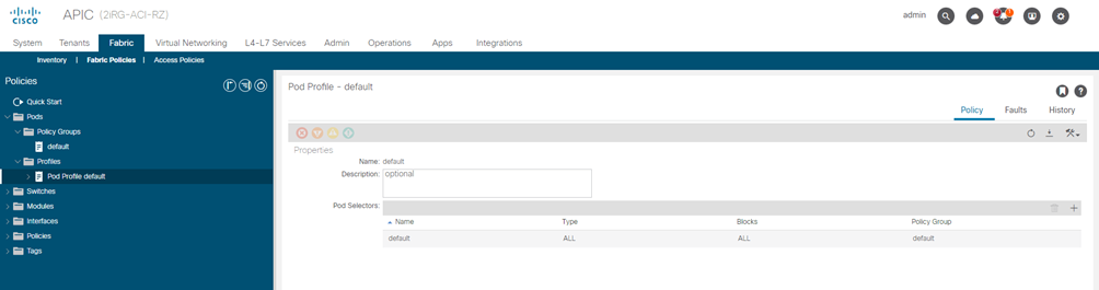
Pod Profile and Policy Group
STEP-1:
Check that the Pod profile contains a Pod policy group.
Navigate to Fabric > Fabric Policies > Pods > Profiles > Pod Profile default.
STEP-2:
If necessary, create a Pod policy group.
- Navigate to Fabric > Fabric Policies > Pods > Policy Groups.
- Right-click Policy Groups and select Create Pod Policy Group.
- Enter the appropriate information and click Submit.
STEP-3:
Assign the new Pod policy group to the default Pod profile.
- Navigate to Fabric > Fabric Policies > Pods > Profiles > Pod Profile default
- Select the default profile.
- Choose the new pod policy group and click Update.
“Lasciare il POD default “
Fabric Access Global Policies
STEP-4:
From the main navigation menu, select Fabric > Access Policies.
STEP-5:
Configure domain
The domain you configure is what you will select from the Nexus Dashboard Orchestrator when adding this site.
- In the left navigation tree, browse to Physical and External Domains > External Routed Domains.
- Right-click the External Routed Domains category and choose Create Layer 3 Domain.
In the Create Layer 3 Domain window, specify the following:
- For the Name field, specify the name the domain,
- For Associated Attachable Entity Profile, select the AEP you created in Step 6.
- For the VLAN Pool, select the VLAN pool you created in Step 5.
- Click Submit.
No additional changes, such as security domains, are required.
| Name VLAN-POOL | Allocation Mode | Encapsulation VLAN-ID | AAEP | L3-Domain |
| msite | static | 4 | msite-aaep | msite-l3 |
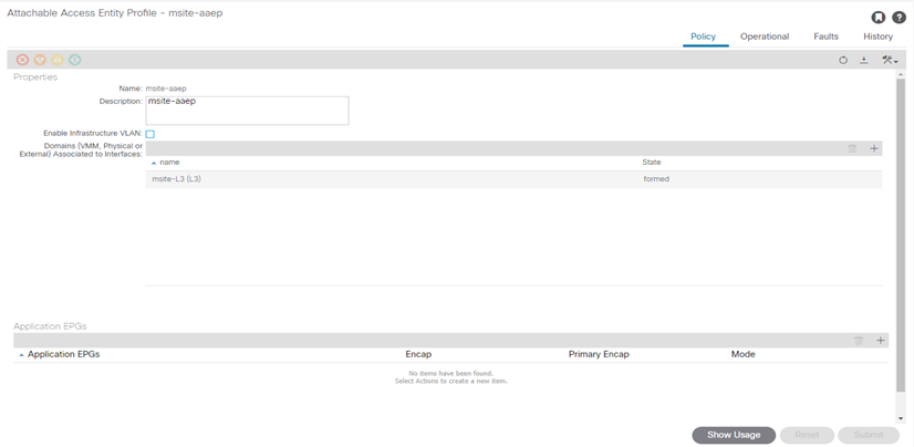
STEP-6:
Configure Attachable Access Entity Profiles (AAEP)
- In the left navigation tree, browse to Global Policies > Attachable Access Entity Profiles.
- Right-click the Attachable Access Entity Profiles category and choose Create Attachable Access Entity Profiles.
In the Create Attachable Access Entity Profiles window, specify the name for the AAEP
- Click Next and Submit
No additional changes, such as interfaces, are required.
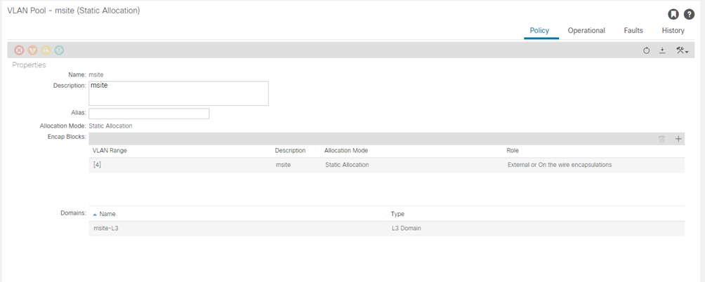
STEP-7:
Specify the VLAN pool
The first thing you configure is the VLAN pool. We use Layer 3 sub-interfaces tagging traffic with VLAN-4 to connect the spine switches to the inter-site network.
- In the left navigation tree, browse to Pools > VLAN.
- Right-click the VLAN category and choose Create VLAN Pool.
In the Create VLAN Pool window, specify the following:
- For the Name field, specify the name for the VLAN pool
- For Allocation Mode, specify Static Allocation.
- And for the Encap Blocks, specify just the single VLAN 4. You can specify a single VLAN by entering the same number in both Range fields.
STEP-8:
From the main navigation menu, select Fabric > Access Policies.
In addition to the VLAN, AEP, and domain you have configured in previous section, you must also create the interface policies for the fabric’s spine switch interfaces that connect to the Inter-Site Network (ISN).
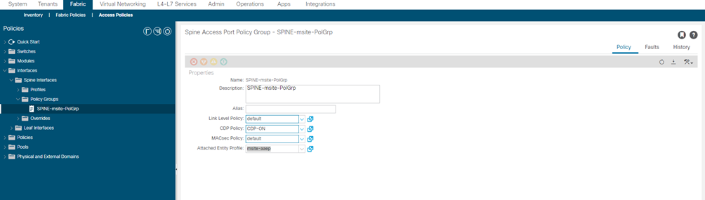
STEP-9:
Configure a spine policy group.
- In the left navigation tree, browse to Interface Policies > Policy Groups > Spine Policy Groups.
This is similar to how you would add a bare-metal server, except instead of a Leaf Policy Group, you are creating a Spine Policy Group.
- Right-click the Spine Policy Groups category and choose Create Spine Access Port Policy Group.
In the Create Spine Access Port Policy Group window, specify the following:
- For the Name field, specify the name for the policy group
- For the Link Level Policy field, specify the link policy used between your spine switch and the ISN.
- For CDP Policy, choose whether you want to enable CDP.
- For the Attached Entity Profile, select the AEP you have configured in previous section
- Click Submit.
No additional changes, such as security domains, are required.
| NAME Policy Group | LINK-LEVEL Policy | CDP Policy | MAC-SEC Policy | AAEP |
| SPINE-msite-PolGrp | default | CDP-ON | Default | msite-aaep |
STEP-10:
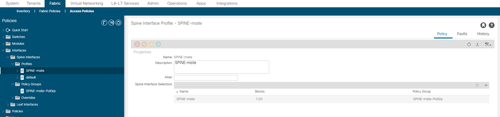
Configure a spine profile.
- In the left navigation tree, browse to Interface Policies > Profiles > Spine Profiles.
- Right-click the Spine Profiles category and choose Create Spine Interface Profile.
In the Create Spine Interface Profile window, specify the following:
- For the Name field, specify the name for the profile,
- For Interface Selectors, click the + sign to add the port on the spine switch that connects to the ISN. Then in the Create Spine Access Port Selector window, provide the following:
- For the Name field, specify the name for the port selector
- For the Interface IDs, specify the switch port that connects to the ISN, for example 1/33.
- For the Interface Policy Group, choose the policy group you created in the previous step
- For Interface Selectors, click the + sign to add the port on the spine switch that connects to the ISN. Then in the Create Spine Access Port Selector window, provide the following:
Then click OK to save the port selector.
- Click Submit to save the spine interface profile.
| NAME SPINE Profile | NAME PORT-SELECTOR | IF-SELECTOR ID | INTERFACE Policy Group |
| SPINE-msite | SPINE-msite | 1/33 | SPINE-msite-PolGrp |
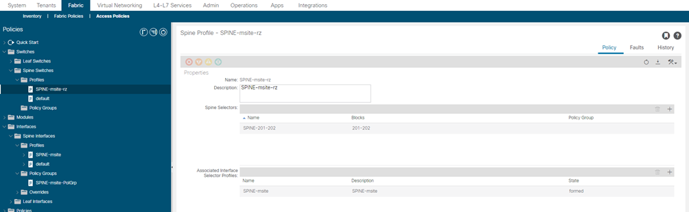
STEP-11:
Configure a spine switch selector policy.
- In the left navigation tree, browse to Switch Policies > Profiles > Spine Profiles.
- Right-click the Spine Profiles category and choose Create Spine Profile.
In the Create Spine Profile window, specify the following:
- For the Name field, specify the name for the profile,
- For Spine Selectors, click the + to add the spine and provide the following:
- For the Name field, specify the name for the selector
- For the Blocks field, specify the spine node, for example 201-202.
- For Spine Selectors, click the + to add the spine and provide the following:
- Click Update to save the selector.
- Click Next to proceed to the next screen.
- Select the interface profile you have created in the previous step
For example Spine-ISN.
- Click Finish to save the spine profile.
| NAME SPINE-SWITCH | NAME SPINE-SELECTOR | Blocks Select Switches | Associated IF selector |
| SPINE-msite-rz | SPINE-201-202 | 201-202 | SPINE-msite |
| SPINE-msite-rz | SPINE-201-202 | 201-202 | SPINE-msite |
| SPINE-msite-cm | SPINE-201-202 | 201-202 | SPINE-msite |
| SPINE-msite-cm | SPINE-201-202 | 201-202 | SPINE-msite |