ACI: Multisite Deploy Steps with MSO (Multisite Orchestrator) Nexus Dashboard versione 2.1.1 – APIC version 4.2(4) and Nexus Spine/Leaf version 14.2(4)
20.02 2024 | by massimilianoArchitettura reale STEP-1: verifica compatibility per APIC versione Link: Cisco Application Policy Infrastructure Controller Release Notes, Release 4.2(4) – Cisco […]
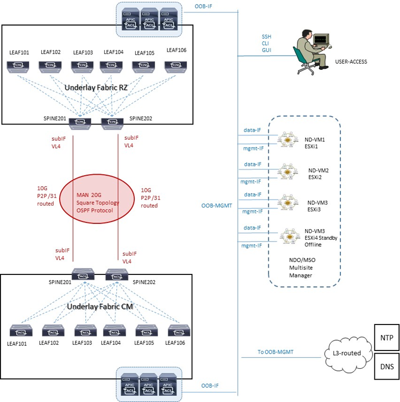
Architettura reale
STEP-1: verifica compatibility per APIC versione
Link: Cisco Application Policy Infrastructure Controller Release Notes, Release 4.2(4) – Cisco
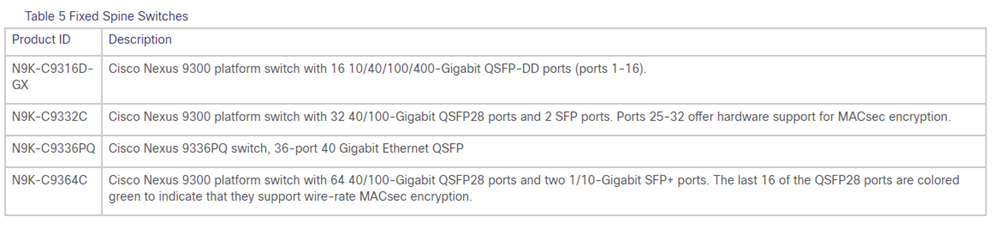
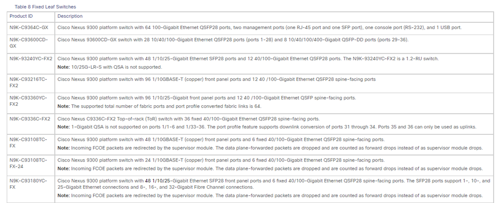
STEP-2: verifica campatibility per Spine and Leaf switches Nexus
Link: Cisco Nexus 9000 ACI-Mode Switches Release Notes, Release 14.2(4) – Cisco
E’ necessario che tutti gli apparati Nexus cosi come i server APIC, abbiano la stessa release software per avere una architettura multisite con Nexus Dashboard; in caso di upgrade versione software seguire gli step successivi
STEP-3: upgrade versione Spine and procedure
STEP-A:
Verify that all the controllers are upgraded to the new firmware version before proceeding.
Do not upgrade the switch firmware until all the controllers are upgraded to the new firmware version first.
STEP-B:
Copy the ACI firmware aci-n9000-dk9.14.2.4i.bin to the switches spine into /bootflash and verify the correct copy into the directory
- dir /bootflash/
CpuUsage.Log MemoryLog.65%usage aci-n9000-dk9.14.0.1h.bin aci-n9000-dk9.14.2.4i.bin auto-k auto-s diagbootup disklog.txt fanfaillog.txt libmon.logs lost+found lxc memlog.txt uribapi_log.txt
STEP-C:
Use the following command to SET and VERIFY the boot variables for the switch:
- clear-bootvars.sh
- setup-clean-config.sh aci-n9000-dk9.14.2.4i.bin
- setup-bootvars.sh aci-n9000-dk9.14.2.4i.bin
- cat /mnt/cfg/0/boot/grub/menu.lst.local
- cat /mnt/cfg/1/boot/grub/menu.lst.local
#General Configuration
#disable certificate
#title bootflash:aci-n9000-dk9.14.2.4i.bin
#boot bootflash:aci-n9000-dk9.14.2.4i.bin
STEP-D:
Reboot the switch
- /user/sbin/chassis-power.cycle.sh
Running INXOS PE IFC image
test sse call id 545
sw card id is 355
STEP-E:
Verify the FPGA e BIOS and manual forced the upgrading of FPGA/EPLD and BIOS
- /bin/check-fpga.sh FpGaDoWnGrAdE
Current log for FPGA images installation:
Could not pull epld logs from plog
Do you want to flash the FPGAs? (yes or no)
yes
!!!WARNING!!!
Don’t touch/powercyle the box until the process is done
or else the box won’t be able to recover
Starting FPGA upgrade …
In progress
Done
/bin/check-fpga.sh: line 58: [: -eq: unary operator expected
Upgrading FPGAs for 21156
%SAFESTR CONSTRAINT: strncats: dmax exceeds max, error code=403
updatetordev_versions IOFPGA: device id 220 and version 17
updatetordevversions MIFPGA0 device id 221 and version 3
updatetordevversions MIFPGA1 device id 221 and version 0
Compatibility check:
Module Type Upgradable Impact Reason
- —– —- ———- ———- ——
1 SUP Yes disruptive Module Upgradable
Retrieving EPLD versions… Please wait.
verifyepldimghdr – hdr->version = 0x1; EPLDIMAGE_VERSION = 0x1
epldgetinfofromhdr: model maibock, hw_changes[] = 0x0, 0x0, 0x0
EPLD golden feature is NOT supported.
Images will be upgraded according to following table:
Module Type EPLD Running-Version New-Version Upg-Required
- —– —- ————- ————— ———– ————
1 SUP MI FPGA 0.003 0.003 No
1 SUP IO FPGA 0.017 0.017 No
All Modules are up to date.
%SAFESTR CONSTRAINT: strncats: dmax exceeds max, error code=403
removed `/bootflash/epld.gimg’
STEP-F:
After the Verify FPGA e BIOS, set the command
- /user/sbin/chassis-power.cycle.sh
STEP-G
Verify the new version upgraded on switch
- show version
Cisco Nexus Operating System (NX-OS) Software
TAC support: http://www.cisco.com/tac
Documents: http://www.cisco.com/en/US/products/ps9372/tsdproductssupportserieshome.html
Copyright (c) 2002-2014, Cisco Systems, Inc. All rights reserved.
The copyrights to certain works contained in this software are
owned by other third parties and used and distributed under
license. Certain components of this software are licensed under
the GNU General Public License (GPL) version 2.0 or the GNU
Lesser General Public License (LGPL) Version 2.1. A copy of each
such license is available at
http://www.opensource.org/licenses/gpl-2.0.php and
http://www.opensource.org/licenses/lgpl-2.1.php
Software
BIOS: version 05.39
kickstart: version 14.2(4i) [build 14.2(4i)]
system: version 14.2(4i) [build 14.2(4i)]
PE: version 4.2(4i)
BIOS compile time: 08/30/2019
kickstart image file is: /bootflash/aci-n9000-dk9.14.2.4i.bin
kickstart compile time: 04/21/2020 09:45:55 [04/21/2020 09:45:55]
system image file is: /bootflash/auto-s
system compile time: 04/21/2020 09:45:55 [04/21/2020 09:45:55]
Hardware
cisco N9K-C9332C (“supervisor”)
Intel(R) Xeon(R) CPU D-1526 @ 1.80GHz with 16204800 kB of memory.
Processor Board ID FDO23370SPL
Device name: spine201
bootflash: 125029376 kB
Kernel uptime is 00 day(s), 02 hour(s), 48 minute(s), 37 second(s)
Last reset at 449000 usecs after Sat Dec 04 14:27:07 2021 UTC
Reason: unknown
System version: 14.2(4i)
Service: module reloaded
plugin
Core Plugin, Ethernet Plugin
MSO/NDP MULTISITE ORCHESTRATOR NEXUS DASHBOARD Best-Practices
Il sistema MSO e/o NDO (Nexus Dashboard Orchestrator) rappresenta la consolle centrale di management inter-site datacenter.
Ciascun Nexus dashboard cluster consiste di n° 3 nodi master; per la versione fisica Nexus dashboard cluster sono anche previsti worker nodes per motivi di scalabilità orizzontale e standby nodes per motivi di recovery in caso di faults master node, mentre per la versione virtuale cloud-cluster solo n° 3 nodes sono supportati.
MSO/NDO non sostituisce la funzione APIC il quale mantiene la gestione ed il controllo della sua Fabric di pertinenza.
MSO/NDO è responsabile di provvedere e gestire intersite (anche detto traffic east-west) tenant e policies di rete per poi andare a propagare queste verso i rispettivi cluster APIC Fabric ACI.
Le principali funzioni del sistema MSO/NDO sono:
- Gestione di regole di accesso attraverso RBAC (Role Based Access Control);
- L’aggiunta, la cancellazione e la modifica di ACI sites;
- L’impiego della dashboard per la verifica dello stato in termini di health, fault e logs per tutte le inter-site policies che sono parte del dominio ACI Fabric;
- Provisionig day-0 che permette il collegamento ed il peering tra Spine dei due site datacenter; questa capacità prevede l’abilitazione del protocollo MP-BGP control-plane e lo scambio di informazioni host-endpoint (MAC + IPv4 addresses)
- Creazione di Tenant con il rilascio di questi nei due site datacenter;
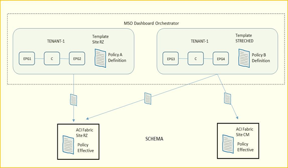
- Definizione di policies template ed associazione di esse ai due site datacenter; le best-practices Cisco raccomandano di gestire tutte le configurazioni per tutti i tenant (object EPG, BD, VRF, Contract) direttamente dal sistema MSO indipendentemente dal fatto che questi oggetti siano streched lungo i due site oppure specifici per un determinato site.
NOTA:
la definizione di “Container” è indicata per uno o più policies-template raggruppati insieme e parte di uno schema; l’associazione di policies di un determinato tenant è comunque sempre definito a livello tenant, non schema.
Requisiti in riferimento alla all’ultima versione Nexus Dashboard 2.1.1 e NDO 3.5.x
NDO è una applicazione a Container che gira su un cluster kubernetes Cisco, incluso nella Nexus Dashboard come hosted application
Per l’installazione della Nexus Dashboard è necessario soddisfare i seguenti step:
- NTP server per il clock sync
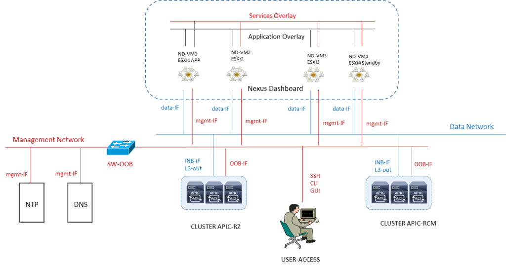
- External Network ND:
- Data Network per la comunicazione tra nodi NDO ed APIC cluster
- Management Network per l’accesso in GUI/CLI/SSH, DNS ed NTP communication, NDO firmware upload, intersight device connector
- Le due reti possono coesistere o meno all’interno di una stessa subnet, seppur le best-practices raccomandano due differenti subnet
- in caso di un cluster fisico (questo post prevede invece VM), la management network deve prevedere la raggiungibilità di ogni nodo via CIMC TCP ports 22/443; NDO cluster utilizza per ogni nodo la CIMC IP address
- Raggiungibilità rete di management OOB del sistema APIC dalla Data Network
- Internal Network ND: due reti supplementari sono necessarie per la comunicazione tra containers utilizzato per il NDO
- una rete /16 come application overlay prepopolata durante il deploy
- una rete /16 come service overlay prepopolata durante il deploy
NOTA: è best-practices che le due reti di cui sopra per la comunicazione del ND cluster siano univoche e differenti dalle reti clienti.
NOTA: I nodi del cluster, se ospiteranno solo MSO/NDO come applicazione, possono essere distribuiti su subnet/siti diversi (non necessitano di essere adiacenti a livello 2).
NOTA: in caso di DCNM (piattaforma offerta da Cisco per l’automazione, controllo e gestione) i nodi debbono essere L2 adjacent per la Data Network con utilizzo di sFlow e/o NetFlow
È raccomandata la disponibilità di un nodo standby sul sito dove è presente un solo master node per mantenere il cluster operativo in caso di indisponibilità del sito con due master.
NOTA. Se abbiamo la necessità di utilizzare altre applicazioni come Nexus Insights allora si dovrà creare un altro cluster su un solo sito.
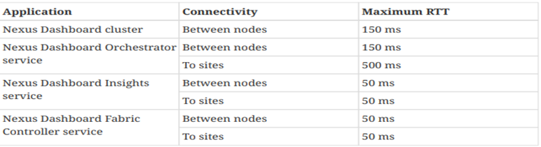
- il massimo valore di RTT tra VM in cluster deve essere minore di 150 ms
- la massima distanza tra il cluster MSO ed APIC non deve superare il valore di 1 sec RTT
- abilitare le seguenti porte utilizzate dal Nexus Dashboard
| Purpose | Port Number | Port Type | Direction |
| Management interface | ICMP | ||
| 22 | TCP | IN | |
| 67,69 | UDP | OUT | |
| 443,5555,9880,30012 | TCP | IN/OUT | |
| 30500-30600 | TCP/UDP | IN/OUT | |
| Data Interface ND between nodes | 53 | TCP/UDP | OUT |
| 443,3379,3380, | TCP | IN/OUT | |
| 4789 | UDP | IN/OUT | |
| 9090,9969,9979,9989,15223 | TCP | IN/OUT | |
| 30002-30006 | TCP | IN/OUT | |
| 30009-30010 | TCP | IN/OUT | |
| 30017 | UDP | IN/OUT | |
| 30025 | TCP | IN/OUT | |
| 30500-30600 | TCP/UDP | IN/OUT | |
| Data Interface on APIC | 22 | TCP | IN |
| 443 | TCP | IN/OUT | |
| Data Interface between ND nodes and Fabric | 443 | TCP | IN/OUT |
| 2022 | TCP | OUT | |
| 5640-5671 | UDP | IN | |
| 5695,5965 | UDP | IN | |
| 8884 | TCP | OUT | |
| 9989 | TCP | IN/OUT | |
| 30000-30001 | TCP | IN |
La connettività tra nodi comunque deve rispettare i seguenti valori RTT (Round Trip Time)
FABRIC CONNECTIVITY DESIGN NEXUS DASHBOARD 2.1.1
Virtual Form Factor and IP addressing network
STEP-1: creazione di un cluster con n° 3 (oppure 4 in caso di VM standby) virtual machine ESXi.ova
STEP-2: IP address planning NTP per i due datacenter RZ e CM
STEP-3: IP address plan per i DNS di ciascun datacenter
STEP-4: assegnazione di un Domain Name
STEP-5: IP address planning Management Network OOB per ciascun datacenter
STEP-6: IP address planning per le Internal Network /16 di cui una per la Services Overlay e l’altra per la Application Overlay
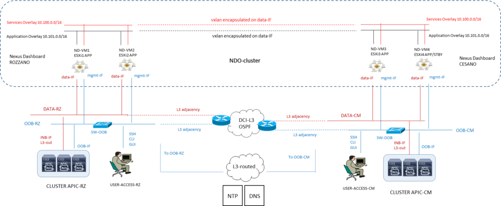
Nexus Dashboard supporta una configurazione di nodi in siti differenti.
Il nodo standby è supportato solo nella versione di ND physical appliance e pertanto nella versione virtualizzata se un nodo fallisce, vi è la necessità di portare UP un nuovo virtual node per sostituire quello in fault.
NOTA: la comunicazione tra container (applicazioni NDO) rilasciati in differenti ND nodes è di tipo VXLAN-encapuslated ed impiega la DATA interface IP come sorgente e destinazione; questo significa che la Application Overlay e la Service Overlay addresses non sono mai esposti al di fuori della DATA network e qualsiasi traffico tra queste subnets è ruotata internamente al cluster.
Vi sono due possibilità di collegare il Nexus Dashboard cluster alla Fabric ACI
- via a Layer 3 network (quella utilizzata in questo progetto)
- via Leaf switches connectivity
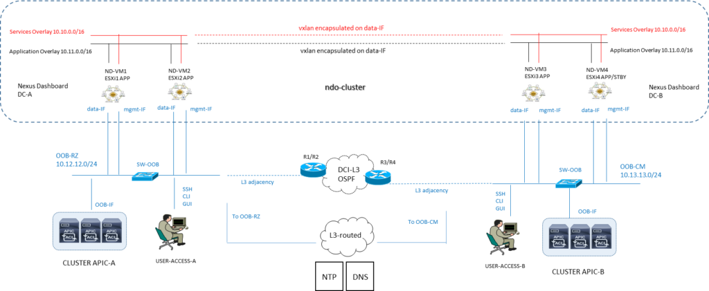
Ipotesi con due reti Data e OOB network:
Ipotesi con la stessa subnet Data e OOB network:
Link Deployment ND:
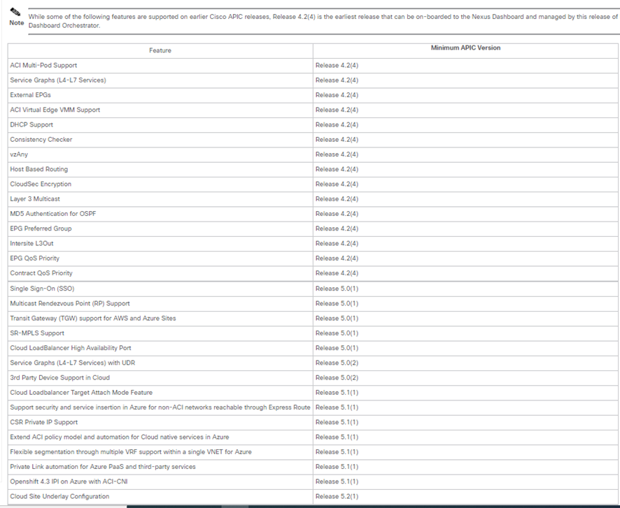
Link Compatibility Fabric 4.2(4) con ND 2.1.1
Cisco Nexus Dashboard and Services Compatibility Matrix
NEXUS DASHBOARD SETUP SOFTWARE PROCESS
STEP-1:
Download the Nexus Dashboard image.
- https://software.cisco.com/download/home
- Choose the Nexus Dashboard version you want to download.
- Download the Cisco Nexus Dashboard image
nd-dk9.2.1.1e.iso - (Optional) Host the image on a web server in your environment.
When you upload the image to your Nexus Dashboard cluster, you will have an option to provide a direct URL to the image.
STEP-2:
Log in to your current Nexus Dashboard GUI as an Administrator user.
STEP-3:
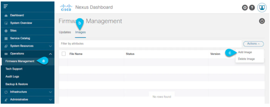
Upload the new image to the cluster.
- Navigate to Operations > Firmware Management.
- Select the Images tab.
- From the Actions menu, select Add Image.
STEP-4:
Select the new image.
- In the Add Firmware Image window, select Local.
Alternatively, if you hosted the image on a web server, choose Remote instead.
- Click Select file and select the ISO image you downloaded in the first step.
If you chose to upload a remote image, provide the file path for the image on the remote server.
- Click Upload to add the image.
The image will be uploaded to the Nexus Dashboard cluster, unpacked, processed, and made available for the upgrade. The whole process may take several minutes and you will be able to see the status of the process in the Images tab.
STEP-5:
Wait for the image status to change to Downloaded.
You can check the status of the image download progress in the Images.
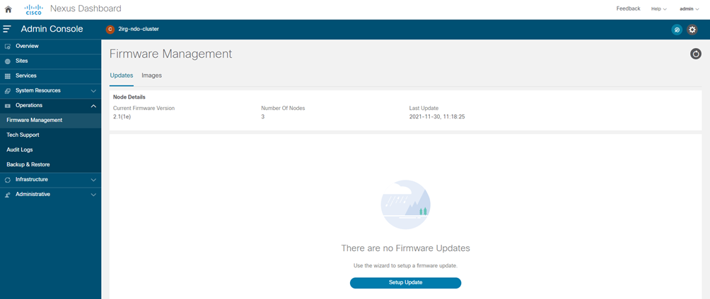
STEP-6:
Setup the update.
- Navigate to Operations > Firmware Management.
- Select the Updates tab.
- Click Setup Update.
The Firmware Update screen opens.
STEP-7:
Choose the upgrade image.
- In the Firmware Update > Version selection screen, select the firmware version you uploaded and click Next.
- In the Firmware Update > Confirmation screen, verify the details and click Begin Install.
The installation progress window is displayed. You can navigate away from this screen while the update is in progress. To check on the update status at a later time, navigate to the Firmware Management screen and click View Details in the Last Update Status tile.
This will set up the required Kubernetes images and services but will not switch the cluster to the new version. The cluster will continue to run the existing version until you activate the new image in the next step. The entire process may take up to 20 minutes.
STEP-8:
Activate the new image.
- Navigate back to the Operations > Firmware Management screen
- In the Last Update Status tile, click View Details.
- Click Activate.
- In the Activation Confirmation window, click Continue.
It may take up to 20 additional minutes for all the cluster services to start and the GUI to become available. The page will automatically reload when the process is completed.
STEP-9:
If you upgraded a virtual cluster deployed in VMware ESX, convert the nodes to the new profile.
| Note | If you upgraded a physical cluster, skip this step. |
Starting with Release 2.1(1) Nexus Dashboard supports two different node profiles for virtual nodes deployed in VMware ESX.
After the upgrade, you must convert all the nodes of the existing cluster to one of the new profiles:
- Data node—node profile designed for data-intensive applications, such as Nexus Dashboard Insights
- App node—node profile designed for non-data-intensive applications, such as Nexus Dashboard Orchestrator
The profile you choose depends on your use case scenario:
- If you plan to run only the Nexus Dashboard Orchestrator service, convert all nodes to the App node profile (nostro caso)
- If you plan to run Nexus Dashboard Insights or co-host applications, you must convert the nodes to the Data profile.
You convert the nodes to the new profile by deploying brand new nodes using that profile and replacing existing nodes with them one at a time.
- Bring down one of the nodes.
You must replace one node at a time.
- Deploy a new node in VMware ESX using the App file nd-dk9.2.1e-app.ova
When deploying the new node, you must use the same exact network configuration parameters as the node you are replacing. You must also ensure that the Cluster Leader checkbox in the OVF parameters is left unchecked.
- Log in to the existing Nexus Dashboard GUI.
You can use the management IP address of one of the remaining healthy master nodes.
- From the left navigation pane, select System Resources > Nodes.
The node you are replacing will be listed as Inactive.
- Click the (…) menu next to the inactive master node you want to replace and select Replace.
The Replace window will open.
- Provide the Management IP Address and Password for the node, then click Verify.
The cluster will connect to the new node’s management IP address to verify connectivity.
- Click Replace.
It may take up to 20 minutes for the node to be configured and join the cluster.
- Wait for the cluster to become healthy, then repeat this step for the other two nodes.
STEP-10:
If you are hosting multiple applications in the same cluster, configure deployment profiles for the App Infra Services.
If you are hosting only a single application in your Nexus Dashboard cluster, skip this step.
If you are co-hosting multiple applications in the same cluster, you must configure the App Infra Services with deployment profiles appropriate for your combination of applications and fabric sizes.
DEPLOY ND with VMware Enviroment ESXi
La compatibilità VMware è indicata nella seguente tabella:
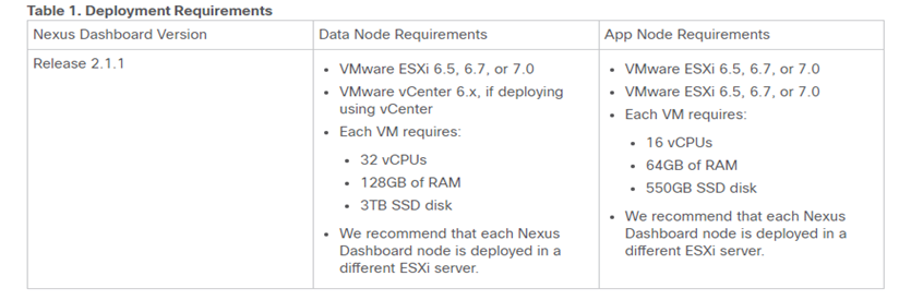
Per gli step di rilascio è necessario seguire le best-practices Cisco indicate dal seguente link:
NOTA CISCO:
- Data Node—node profile designed for data-intensive applications, such Nexus Dashboard Insights
- App Node—node profile designed for non-data-intensive applications, such Nexus Dashboard Orchestrator
- After each node’s VM has deployed, ensure that the VMware Tools periodic time synchronization has disabled as described in the deployment procedure.
- VMware Distributed Resource Scheduler (DRS) has not supported for Nexus Dashboard cluster nodes.
- You can choose to deploy the nodes directly in ESXi or using vCenter.
- If you want to deploy using vCenter, following the steps described in Deploying Cisco Nexus Dashboard Using VMware vCenter.
- If you want to deploy directly in ESXi, following the steps described in Deploying Cisco Nexus Dashboard Directly in VMware ESXi.
Cluster and Node Setup Planning
STEP-1: cluster setup
| PARAMETER | DETAIL CONFIGURATION |
| Cluster Name | |
| NTP Server IP address | |
| DNS Provider IP address | |
| DNS Search Domain name | |
| Application Network Subnet IP | 10.101.0.0/16 |
| Services Network Subnet IP | 10.100.0.0/16 |
STEP-2: node setup
| DATACENTER | OOB SUBNET | INTERFACE | OOB IP VM | OOB GW | HOSTNAME |
| RZ | MGMT (bond1br) | vm-ndo-1 (master) | |||
| RZ | DATA (bond0br) | vm-ndo-1 (master) | |||
| RZ | MGMT (bond1br) | vm-ndo-2 (master) | |||
| RZ | DATA (bond0br) | vm-ndo-2 (master) | |||
| CM | MGMT (bond1br) | vm-ndo-3 (master) | |||
| CM | DATA (bond0br) | vm-ndo-3 (master) | |||
| CM | MGMT | vm-ndo-4 (offline) | |||
| CM | DATA | vm-ndo-4 (offline) |
STEP-3: setup password per tutti i nodi
STEP-4: internal subnets setup
| DATACENTER | SUBNET | OVERLAY | INTERFACE | INTERNAL TYPE | GATEWAY | HOSTNAME |
| RZ | 10.100.0.0/16 | Services-Overlay | lo:service | SERVICES | <nil> | vm-ndo-1 |
| RZ | 10.101.0.0/16 | Application-Overlay | app-vnic | APPLICATION | <nil> | vm-ndo-1 |
| RZ | 10.100.0.0/16 | Services-Overlay | lo:service | SERVICES | <nil> | vm-ndo-2 |
| RZ | 10.101.0.0/16 | Application-Overlay | app-vnic | APPLICATION | <nil> | vm-ndo-2 |
| CM | 10.100.0.0/16 | Services-Overlay | lo:service | SERVICES | <nil> | vm-ndo-3 |
| CM | 10.101.0.0/16 | Application-Overlay | app-vnic | APPLICATION | <nil> | vm-ndo-3 |
| CM | 10.100.0.0/16 | Services-Overlay | lo:service | SERVICES | <nil> | vm-ndo-4 |
| CM | 10.101.0.0/16 | Application-Overlay | app-vnic | APPLICATION | <nil> | vm-ndo-4 |
DEPLOY NDO 3.5.1
NDO è un’applicazione per Nexus Dashboard che prevede i seguenti requisiti:
Gli step di configurazione debbono seguire le best-practices indicate nel seguente link:
NEXUS DASHBOARD ORCHESTRATOR ADDING SITE
STEP-1:
Log in to the Nexus Dashboard GUI
STEP-2:
Add a new site
- From the left navigation menu, select Sites.
- In the top right of the main pane, select Actions > Add Site.
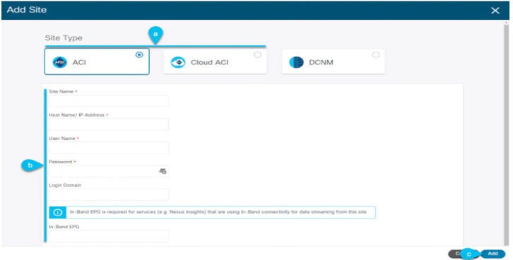
STEP-3:
Provide site information
- For Site Type, select ACI or Cloud ACI depending on the type of ACI fabric you are adding.
- Provide the controller information.
You need to provide the Host Name/IP Address, User Name, and Password for the APIC controller currently managing your ACI fabrics.
| Note | For APIC fabrics, if you will use the site with Nexus Dashboard Orchestrator service only, you can provide either the in-band or out-of-band IP address of the APIC. If you will use the site with Nexus Dashboard Insights as well, you must provide the in-band IP address. |
For on-premises ACI sites managed by Cisco APIC, if you plan to use this site with Day-2 Operations applications such as Nexus Insights, you must also provide the In-Band EPG name used to connect the Nexus Dashboard to the fabric you are adding.
Otherwise, if you will use this site with Nexus Dashboard Orchestrator only, you can leave this field blank.
- Click Add to finish adding the site.
At this time, the sites will be available in the Nexus Dashboard, but you still need to enable them for Nexus Dashboard Orchestrator management as described in the following steps.
STEP-4:
Repeat the previous steps for any additional ACI sites.
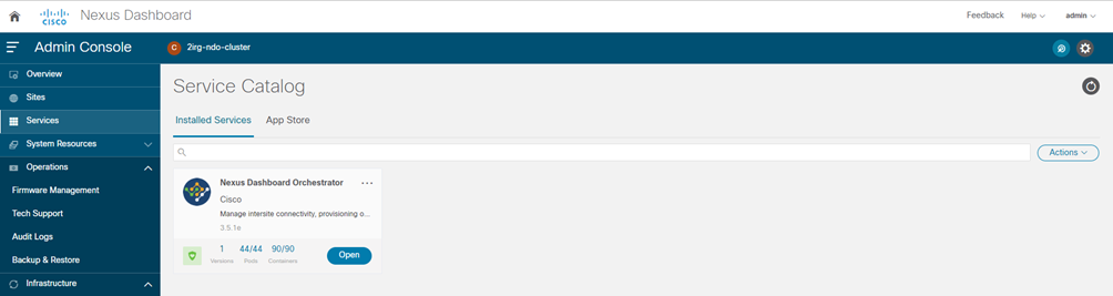
STEP-5:
From the Nexus Dashboard’s Service Catalog, open the Nexus Dashboard Orchestrator service.
You will be automatically logged in using the Nexus Dashboard user’s credentials.
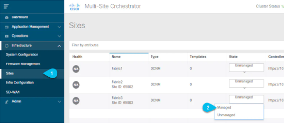
STEP-6:
In the Nexus Dashboard Orchestrator GUI, manage the sites
- From the left navigation menu, select Infrastructure > Sites.
- In the main pane, change the State from
UnmanagedtoManagedfor each fabric that you want the NDO to manage.
NEXUS DASHBOARD ORCHESTRATOR SETUP MANUALLY
STEP-1:
Download the Cisco Nexus Dashboard Orchestrator service.
File: Cisco-MSO-3.5.1e.aci
https://software.cisco.com/download/home
- Browse to the Nexus Dashboard Orchestrator download page:
- From the left navigation menu, select the 3.5.1 release
- Click the download icon next to the
.napimage. - Click Agree and download to accept the license agreement and download the image.
STEP-2:
Log in to your Cisco Nexus Dashboard dashboard.
When deploying an app, you need to install it in only one of the Nexus Dashboard nodes, the application will be replicated to the other nodes in the cluster automatically. So you can log in to any one of your Nexus Dashboard nodes using its management IP address.
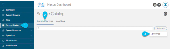
STEP-3:
Upload the app image.
- In the left navigation bar, click Service Catalog.
- Select the Installed Services tab.
- In the top right of the main pane, select Actions > Upload App.
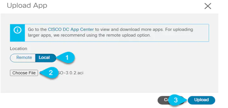
STEP-4:
Upload the image file to the Nexus Dashboard cluster
- Choose the location of the image.
If you downloaded the application image to your system, choose Local.
If you are hosting the image on a server, choose Remote.
- Choose the file.
If you chose Local in the previous substep, click Select File and select the app image you downloaded.
If you chose Remote, provide the full URL to the image file, for example http://<ip-address>:<port>/<full-path>/cisco-mso-<version>.aci.
- Click Upload to add the app to the cluster.
STEP-5:
Wait for the application to be downloaded to the Nexus Dashboard and deployed.
It may take up to 30 minutes for the application to replicate to all nodes and all services to fully deploy.
STEP-6:
Enable the app.
After installation is complete, the application will remain in the Disabled state by default and you must enable it.
To enable the app, click the … menu on the app and select Enable.
STEP-7:
Launch the app.
To launch the app, simply click Open on the application tile in the Nexus Dashboard’s Service Catalog page; the single sign-on (SSO) feature allows you to log in to the application using the same credentials as you used for the Nexus Dashboard.
NEXUS DASHBOARD ORCHESTRATOR DAY-0 CONFIGURATION ACI
Pod Profile and Policy Group (configuration by APIC site)
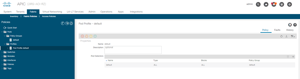
STEP-1:
Check that the Pod profile contains a Pod policy group.
Navigate to Fabric > Fabric Policies > Pods > Profiles > Pod Profile default.
STEP-2:
If necessary, create a Pod policy group.
- Navigate to Fabric > Fabric Policies > Pods > Policy Groups.
- Right-click Policy Groups and select Create Pod Policy Group.
- Enter the appropriate information and click Submit.
STEP-3:
Assign the new Pod policy group to the default Pod profile.
- Navigate to Fabric > Fabric Policies > Pods > Profiles > Pod Profile default
- Select the default profile.
- Choose the new pod policy group and click Update.
“Lasciare il POD default “
Fabric Access Global Policies (configuration by APIC site)
STEP-4:
From the main navigation menu, select Fabric > Access Policies.
STEP-5:
Configure Attachable Access Entity Profiles (AAEP).
- In the left navigation tree, browse to Global Policies > Attachable Access Entity Profiles.
- Right-click the Attachable Access Entity Profiles category and choose Create Attachable Access Entity Profiles.
In the Create Attachable Access Entity Profiles window, specify the name for the AAEP
- Click Next and Submit
No additional changes, such as interfaces, are required.
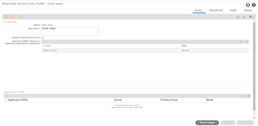
STEP-6:
Configure domain.
The domain you configure is what you will select from the Nexus Dashboard Orchestrator when adding this site.
- In the left navigation tree, browse to Physical and External Domains > External Routed Domains.
- Right-click the External Routed Domains category and choose Create Layer 3 Domain.
In the Create Layer 3 Domain window, specify the following:
- For the Name field, specify the name the domain,
- For Associated Attachable Entity Profile, select the AEP you created in Step 6.
- For the VLAN Pool, select the VLAN pool you created in Step 5.
- Click Submit.
No additional changes, such as security domains, are required.
| Name VLAN-POOL | Allocation Mode | Encapsulation VLAN-ID | AAEP | L3-Domain |
| msite | static | 4 | msite-aaep | msite-l3 |
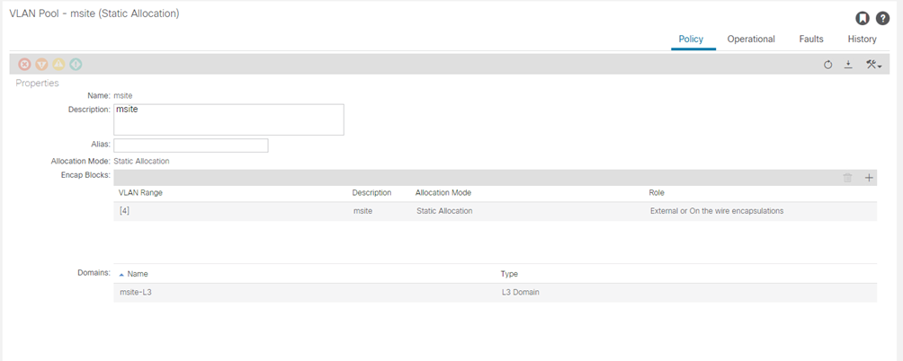
STEP-7:
Specify the VLAN pool.
The first thing you configure is the VLAN pool. We use Layer 3 sub-interfaces tagging traffic with VLAN-4 to connect the spine switches to the inter-site network.
- In the left navigation tree, browse to Pools > VLAN.
- Right-click the VLAN category and choose Create VLAN Pool.
In the Create VLAN Pool window, specify the following:
- For the Name field, specify the name for the VLAN pool
- For Allocation Mode, specify Static Allocation.
- And for the Encap Blocks, specify just the single VLAN 4. You can specify a single VLAN by entering the same number in both Range fields.
STEP-8:
From the main navigation menu, select Fabric > Access Policies.
In addition to the VLAN, AAEP, and domain you have configured in previous section, you must also create the interface policies for the fabric’s spine switch interfaces that connect to the Inter-Site Network (ISN).
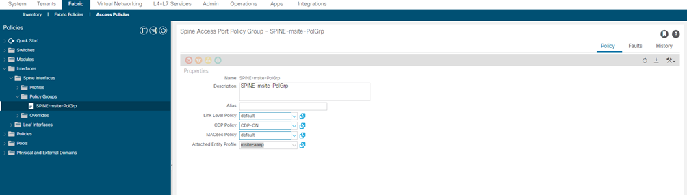
STEP-9:
Configure a spine policy group.
- In the left navigation tree, browse to Interface Policies > Policy Groups > Spine Policy Groups.
This is similar to how you would add a bare-metal server, except instead of a Leaf Policy Group, you are creating a Spine Policy Group.
- Right-click the Spine Policy Groups category and choose Create Spine Access Port Policy Group.
In the Create Spine Access Port Policy Group window, specify the following:
- For the Name field, specify the name for the policy group
- For the Link Level Policy field, specify the link policy used between your spine switch and the ISN.
- For CDP Policy, choose whether you want to enable CDP.
- For the Attached Entity Profile, select the AEP you have configured in previous section
- Click Submit.
No additional changes, such as security domains, are required.
| NAME Policy Group | LINK-LEVEL Policy | CDP Policy | MAC-SEC Policy | AAEP |
| SPINE-msite-PolGrp | default | CDP-ON | Default | msite-aaep |
STEP-10:
Configure a spine profile.
- In the left navigation tree, browse to Interface Policies > Profiles > Spine Profiles.
- Right-click the Spine Profiles category and choose Create Spine Interface Profile.
In the Create Spine Interface Profile window, specify the following:
- For the Name field, specify the name for the profile,
- For Interface Selectors, click the + sign to add the port on the spine switch that connects to the ISN. Then in the Create Spine Access Port Selector window, provide the following:
- For the Name field, specify the name for the port selector
- For the Interface IDs, specify the switch port that connects to the ISN, for example 1/33.
- For the Interface Policy Group, choose the policy group you created in the previous step
- For Interface Selectors, click the + sign to add the port on the spine switch that connects to the ISN. Then in the Create Spine Access Port Selector window, provide the following:
Then click OK to save the port selector.
- Click Submit to save the spine interface profile.
| NAME SPINE Profile | NAME PORT-SELECTOR | IF-SELECTOR ID | INTERFACE Policy Group |
| SPINE-msite | SPINE-msite | 1/33 | SPINE-msite-PolGrp |
STEP-11:
Configure a spine switch selector policy.
- In the left navigation tree, browse to Switch Policies > Profiles > Spine Profiles.
- Right-click the Spine Profiles category and choose Create Spine Profile.
In the Create Spine Profile window, specify the following:
- For the Name field, specify the name for the profile,
- For Spine Selectors, click the + to add the spine and provide the following:
- For the Name field, specify the name for the selector
- For the Blocks field, specify the spine node, for example 201-202.
- For Spine Selectors, click the + to add the spine and provide the following:
- Click Update to save the selector.
- Click Next to proceed to the next screen.
- Select the interface profile you have created in the previous step
For example Spine-ISN.
- Click Finish to save the spine profile.
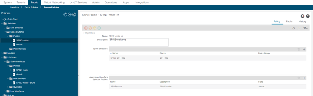
| NAME SPINE-SWITCH | NAME SPINE-SELECTOR | Blocks Select Switches | Associated IF selector |
| SPINE-msite-rz | SPINE-201-202 | 201-202 | SPINE-msite |
| SPINE-msite-rz | SPINE-201-202 | 201-202 | SPINE-msite |
| SPINE-msite-cm | SPINE-201-202 | 201-202 | SPINE-msite |
| SPINE-msite-cm | SPINE-201-202 | 201-202 | SPINE-msite |