Networking L2circuit (L2VPN underlay and overlay) over mpls
24.03 2022 | by massimilianoQuesto post si pone l’obiettivo di realizzare una carellata di network design attraverso i quali in modo semplice si cerca […]
https://www.ingegnerianetworking.com/wp-content/uploads/2022/03/l2-pc-a79.png
Questo post si pone l’obiettivo di realizzare una carellata di network design attraverso i quali in modo semplice si cerca di evidenziarne i circuiti che sono interessati.
Ovviamente è bene partire dal caso più semplice che riguarda il collegamento di due host con la stessa prefix direttamente collegati a livello 2 (switching)
LAN L2-only
L’architettura è la seguente:
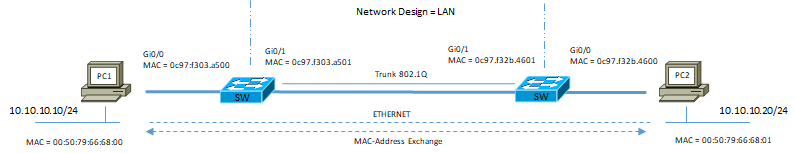
A tempo zero abbiamo la sola tabella di MAC address popolata dai rispettivi SW1 e SW2 come da seguente output
SW1#show mac address-table
Mac Address Table
- ——————————————
Vlan Mac Address Type Ports
- — ———– ——– —–
1 0c97.f32b.4601 DYNAMIC Gi0/1 # lo switch 1 impara il mac-address della interfaccia di fronte ad esso (mac-address SW2 gi0/1)
Total Mac Addresses for this criterion: 1
SW1#
SW2#show mac address-table
Mac Address Table
- ——————————————
Vlan Mac Address Type Ports
- — ———– ——– —–
1 0c97.f303.a501 DYNAMIC Gi0/1 # lo switch 2 impara il mac-address della interfaccia di fronte ad esso (mac-address SW1 gi0/1)
Total Mac Addresses for this criterion: 1
SW2#
Per poter imparare anche i MAC address dei rispettivi PC è necessario che uno di loro faccia partire un ping (pacchetto ICMP) verso la sua destinazione
PC1> ping 10.10.10.20
84 bytes from 10.10.10.20 icmp_seq=1 ttl=64 time=8.316 ms
84 bytes from 10.10.10.20 icmp_seq=2 ttl=64 time=9.451 ms
84 bytes from 10.10.10.20 icmp_seq=3 ttl=64 time=10.119 ms
84 bytes from 10.10.10.20 icmp_seq=4 ttl=64 time=9.249 ms
Ora la tabella dei MAC address dei rispettivi SW è la seguente:
SW1#show mac address-table
Mac Address Table
- ——————————————
Vlan Mac Address Type Ports
- — ———– ——– —–
1 0050.7966.6800 DYNAMIC Gi0/0
1 0050.7966.6801 DYNAMIC Gi0/1
1 0c97.f32b.4601 DYNAMIC Gi0/1
Total Mac Addresses for this criterion: 3
SW1#
SW2#show mac address-table
Mac Address Table
- ——————————————
Vlan Mac Address Type Ports
- — ———– ——– —–
1 0050.7966.6800 DYNAMIC Gi0/1
1 0050.7966.6801 DYNAMIC Gi0/0
1 0c97.f303.a501 DYNAMIC Gi0/1
Total Mac Addresses for this criterion: 3
SW2#
LAN – Campus – DataCenter Legacy (Inter-Vlan Routing)
L’architettura di riferimento è la seguente:
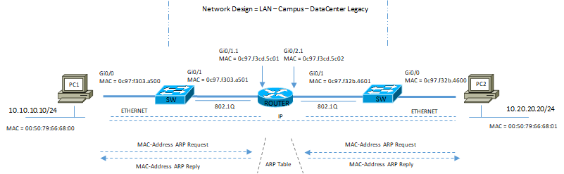
A tempo zero abbiamo la seguente condizione:
SW1# show mac address-table
Mac Address Table
- ——————————————
Vlan Mac Address Type Ports
- — ———– ——– —–
1 0050.7966.6800 DYNAMIC Gi0/0
1 0c97.f3cd.5c01 DYNAMIC Gi0/1
Total Mac Addresses for this criterion: 2
SW1#
SW2#show mac address-table
Mac Address Table
- ——————————————
Vlan Mac Address Type Ports
- — ———– ——– —–
1 0050.7966.6801 DYNAMIC Gi0/0
1 0c97.f3cd.5c02 DYNAMIC Gi0/2
Total Mac Addresses for this criterion: 2
SW2#
Dal punto di vista del router:
R1#show ip arp
Protocol Address Age (min) Hardware Addr Type Interface
Internet 10.10.10.1 – 0c97.f3cd.5c01 ARPA GigabitEthernet0/1.1
Internet 10.10.10.10 2 0050.7966.6800 ARPA GigabitEthernet0/1.1
Internet 10.20.20.1 – 0c97.f3cd.5c02 ARPA GigabitEthernet0/2.1
Internet 10.20.20.20 2 0050.7966.6801 ARPA GigabitEthernet0/2.1
R1#
Questi due semplici esempi sono solo introduttivi per andare ad esaminare network design molti più complessi indicati dalla seguente figura:
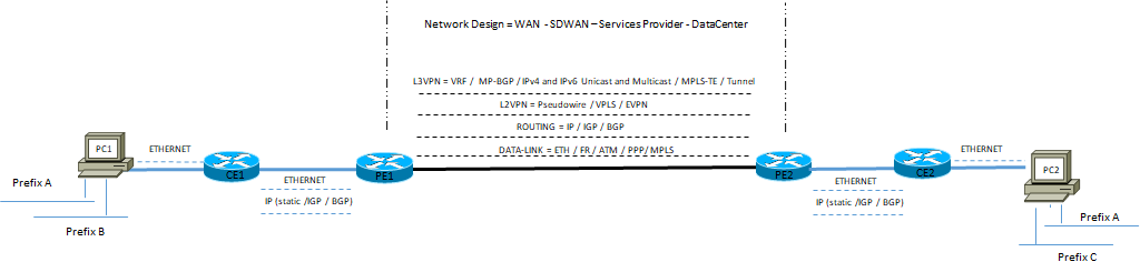
L2VPN Topology Design
- Layer 2 VPN: sono trasportate frame layer 2 attraverso una rete MPLS aware
- – LSP provvedono ad una connessione end-to-end MPLS rachability tra due end-point routers (transport LSP or tunnel LSP)
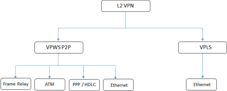
- – VPN point-to-point sono chiamate virtual private wire service (VPWS) oppure Pseudowire
- – VPN Multi point-to-point chiamate virtual privat lan services (VPLS)
Sia VPWS che VPLS possono essere create attraverso il metodo Kompella oppure Martini; in entrambi i metodi l’LSP è costruito tra due PE attraverso il protocollo LDP.
Per i circuiti L2 pseudowire con il metodo Kompella il trasporto delle labels è segnalato via LDP a differenza della VC (virtual circuit) dove la label è segnalata via MP-BGP; mentre con il metodo Martini entrambe le labels via LDP.
Il PE routers MPLS, collegato al CE customer devices, analizza la frame ethernet in ingresso e identifica quale egress router PE è usato per il trasporto della frame (primo lookup); il secondo lookup determina l’interfaccia egress presso il router PE egress
I pacchetti MPLS Layer 2 utilizzano due labels:
- – Outer Label (topmost) utizzata per raggiungere il devices egress (di uscita)
- – Inner Label (VC label) utilizzata per identificare il circuito pseudowire at Egress router PE
VPWS può trasportare qualsiasi payload layer 2; VPLS trasporta solo frame ethernet; in VPWS i PE routers imparano solo VLAN se il VC-type è VLAN (se il VC-type è ethernet, i PE routers non apprendono le informazioni VLAN)
Per VPWS esiste un solo punto di uscita presso il router PE egress, quindi questo significa che i PE MPLS non hanno necessità di mantenere una tabella di MAC addresses per la costruzione del PW.
Viceversa per VPLS, ricordiamo che il PE emula un dominio di bridge verso il customer CE, la rilegatura tra MAC addresses e circuito pesudowire è necessaria (essendo VPLS multipoint-to-multipoint, la destinazione di una frame può essere qualsiasi PE egress appartenente al domino VPLS).
In terminologia Junos L2VPN hanno i seguenti nomi:
CCC (Circuit Cross-Connect) i quali non richiedono segnalazione (no BGP, LDP) ed in questo modo sia il servizio che il trasporto non sono disaccoppiati ed ogni trasporto LSP (tunnel mpls) è dedicato ad un servizio.
In questo caso, quindi abbiamo un rapporto 1:1 service to trasport L2VPN
TCC (Translation Cross-Connect) è generalmente applicato a servizi conosciuto come L2,5VPN (sono servizi dove i rispettivi AC Attachment Circuit alle due estremità di un collegamento PE-CE hanno tecnologie differenti, ad esempio Ethernet uno ed ATM l’altro.
La tabella seguente indica differenti L2VPN riguardo la topologia ed il protocollo di segnalazione impiegato:
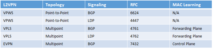
Altre topologie di L2VPN basate su differenti encapsulation sono:
PBB (Provider Backbone Bridging)
MAC in MAC
VPLS-PBB (RFC 7041)
EVPN-PBB (RFC 7623)
Per la parte L2 EVPN Load-balancing, CE customer collegati in dual-homed allo stesso o differente VPLS-PE router del Services Provider, possono utilizzare i due link in modalità active-standby per tutte le vlans oppure utilizzare un vlan-based load-balancing (50% di vlan su un link e l’altro 50% di vlan sull’altro).
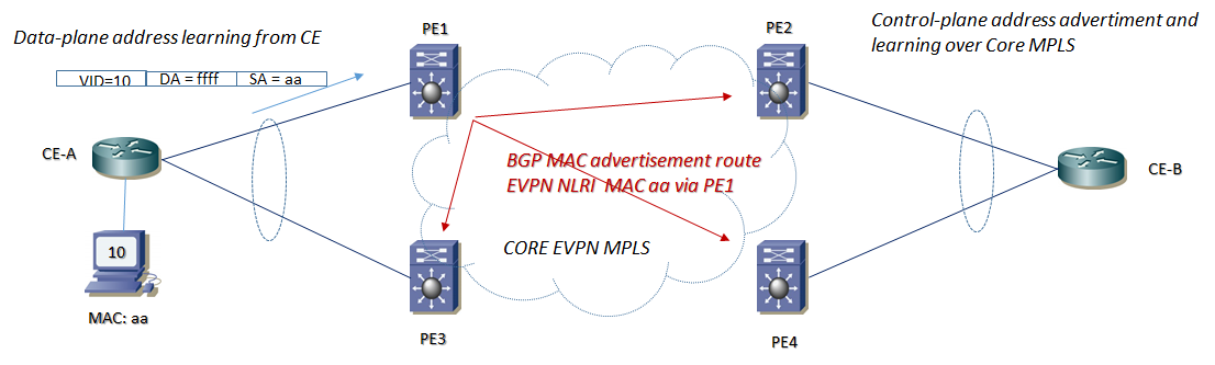
EVPN (Ethernet VPN) è la nuova generazione per MPLS ethernet based services (VPLS) può supportare invece active-active flow-based load-balancing e le vlans possono essere utilizzate in entrambi i links attivamente; questo significa anche fast-convergence customer links, PE links ed node failure scenario.
In VPLS la tabella di learning MAC addresses è imparata via data-plane (piano di forwarding) e segnalata attraverso MP-BGP control-plane; in EVPN non esiste un data-plane MAC learning attraverso il Core Network, ma il MAC addresses è appreso direttamente dal circuito layer 2 direttamente connesso ai due end-point routers, sempre via data-plane
Torniamo ora sulla parte di Test LAB per la parte L2VPN Pswudowire
L’architettura di riferimento è la seguente:
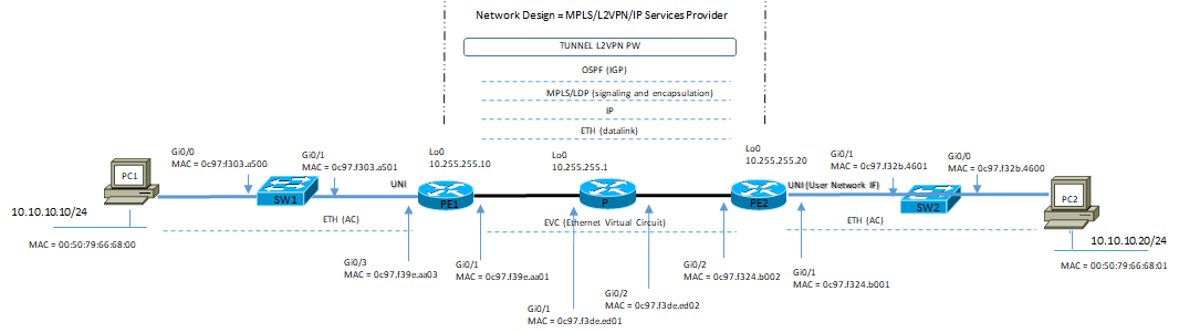
Vi sono tre tipi di EVC:
- – E-Line: è un servizio punto-punto (una associazione tra due UNI)
- – E-LAN: è un servizio multipunto-multipunto (una associazione tra tre o più UNI in modo simile a quanto avviene in una rete broadcast)
- – E-Tree: è un servizio rooted-multipoint (una associazione tra tre o più UNI in cui da una particolare UNI di root è possibile raggiungere le altre)
- Per ciascuna EVC ci sono due topologie di servizio;
- – Port-Based: tutte le trame ETH entranti in una UNI sono associate ad un unico EVC, indipendentemente dal valore di Vlan-ID
- – VLAN-Based: ad ogni Vlan-ID si fa corrispondere in modo esplicito un EVC (è possibile far corrispondere un insieme di Vlan-ID ad una unica EVC)
Vediamo ora aspetti di configurazione base:
SW1
vlan 10
name test-10
!
interface GigabitEthernet0/0
description to PC1
switchport access vlan 10
switchport mode access
media-type rj45
negotiation auto
!
interface GigabitEthernet0/1
description to-PE1
switchport trunk encapsulation dot1q
switchport mode trunk
!
PE1
pseudowire-class PW
encapsulation mpls
!
interface Loopback0
description RID
ip address 10.255.255.10 255.255.255.255
ip ospf 1 area 0.0.0.0
!
interface GigabitEthernet0/1
description backbone
ip address 1.1.1.1 255.255.255.252
ip ospf 1 area 0.0.0.0
mpls label protocol ldp
mpls ip
!
interface GigabitEthernet0/3.10
description L2VPN-Pseudowire
encapsulation dot1Q 10
xconnect 10.255.255.20 10 encapsulation mpls pw-class PW
!
router ospf 1
router-id 10.255.255.10
!
P-router
interface Loopback0
ip address 10.255.255.1 255.255.255.255
ip ospf 1 area 0.0.0.0
!
interface GigabitEthernet0/1
description to-PE1
ip address 1.1.1.2 255.255.255.252
ip ospf 1 area 0.0.0.0
mpls label protocol ldp
mpls ip
!
interface GigabitEthernet0/2
description to-PE2
ip address 1.1.1.5 255.255.255.252
ip ospf 1 area 0.0.0.0
mpls label protocol ldp
mpls ip
!
router ospf 1
router-id 10.255.255.1
!
PE2
pseudowire-class PW
encapsulation mpls
!
interface Loopback0
ip address 10.255.255.20 255.255.255.255
ip ospf 1 area 0.0.0.0
!
interface GigabitEthernet0/1.10
description L2VPN-Pseudowire
encapsulation dot1Q 10
xconnect 10.255.255.10 10 encapsulation mpls pw-class PW
!
interface GigabitEthernet0/2
description backbone
ip address 1.1.1.6 255.255.255.252
ip ospf 1 area 0.0.0.0
mpls label protocol ldp
mpls ip
!
router ospf 1
router-id 10.255.255.20
!
SW2
vlan 10
name test-10
!
interface GigabitEthernet0/0
description to PC2
switchport access vlan 10
switchport mode access
media-type rj45
negotiation auto
!
interface GigabitEthernet0/3
description to-L2VPN
switchport trunk allowed vlan 10
switchport trunk encapsulation dot1q
switchport mode trunk
!
Output di verifica:
PE1#show mpls forwarding-table
Local Outgoing Prefix Bytes Label Outgoing Next Hop
Label Label or Tunnel Id Switched interface
16 No Label l2ckt(10) 7526 Gi0/3.10 point2point
17 Pop Label 10.255.255.1/32 0 Gi0/1 1.1.1.2
18 Pop Label 1.1.1.4/30 0 Gi0/1 1.1.1.2
19 17 10.255.255.20/32 0 Gi0/1 1.1.1.2
PE1#
!
PE1#show ip arp
Protocol Address Age (min) Hardware Addr Type Interface
Internet 1.1.1.1 – 0c97.f39e.aa01 ARPA GigabitEthernet0/1
Internet 1.1.1.2 97 0c97.f3de.ed01 ARPA GigabitEthernet0/1
PE1#
PE1#show mpls l2transport vc 10
Local intf Local circuit Dest address VC ID Status
- ———— ————————– ————— ———- ———-
Gi0/3.10 Eth VLAN 10 10.255.255.20 10 UP
PE1#show mpls l2transport binding 10
Destination Address: 10.255.255.20,VC ID: 10
Local Label: 16
Cbit: 1, VC Type: Ethernet, GroupID: 5
MTU: 1500, Interface Desc: L2VPN-Pseudowire
VCCV: CC Type: CW [1], RA [2]
CV Type: LSPV [2]
Remote Label: 19
Cbit: 1, VC Type: Ethernet, GroupID: 3
MTU: 1500, Interface Desc: L2VPN-Pseudowire
VCCV: CC Type: CW [1], RA [2]
CV Type: LSPV [2]
PE2#show mpls forwarding-table
Local Outgoing Prefix Bytes Label Outgoing Next Hop
Label Label or Tunnel Id Switched interface
16 Pop Label 1.1.1.0/30 0 Gi0/2 1.1.1.5
17 Pop Label 10.255.255.1/32 0 Gi0/2 1.1.1.5
18 16 10.255.255.10/32 0 Gi0/2 1.1.1.5
19 No Label l2ckt(10) 151654 Gi0/1.10 point2point
PE2#
PE2#show ip arp
Protocol Address Age (min) Hardware Addr Type Interface
Internet 1.1.1.5 93 0c97.f3de.ed02 ARPA GigabitEthernet0/2
Internet 1.1.1.6 – 0c97.f324.b002 ARPA GigabitEthernet0/2
PE2#show mpls l2transport vc 10
Local intf Local circuit Dest address VC ID Status
- ———— ————————– ————— ———- ———-
Gi0/1.10 Eth VLAN 10 10.255.255.10 10 UP
PE2#show mpls l2transport binding 10
Destination Address: 10.255.255.10,VC ID: 10
Local Label: 19
Cbit: 1, VC Type: Ethernet, GroupID: 3
MTU: 1500, Interface Desc: L2VPN-Pseudowire
VCCV: CC Type: CW [1], RA [2]
CV Type: LSPV [2]
Remote Label: 16
Cbit: 1, VC Type: Ethernet, GroupID: 5
MTU: 1500, Interface Desc: L2VPN-Pseudowire
VCCV: CC Type: CW [1], RA [2]
CV Type: LSPV [2]
I circuiti L2VPN Pseudowire, come abbiamo visto, sono di tipo punto-punto in grado di trasportare trame ethernet con una emulazione di circuito; in questo caso non viene eseguito nessun processo di MAC Learning in quanto non necessario.
Viceversa in un servizio di tipo VPLS (Virtual Private Lan Services) il processo di MAC Learning è fondamentale e viene eseguito a livello di dataplane.
Per la parte di configurazione VPLS si riportano i concetti base:
Per ogni PE, dove sono attestati le reti clienti, sono create delle istanze L2 Ethernet virtuali conosciute come VSI (Virtual Switch Instance) e viene vista come un insieme di due elementi:
- – VFI (Virtual Forwarding Instance = MAC table)
- – Bridge-Domain: un insieme di interfacce ethernet fisiche o logiche che formano un dominio di broadcast
Esempio base di Configurazione PE
Routed Pseusowire e VPLS con discovery manuale:
interface bdi10
ip address 10.10.10.100 255.255.255.0
no shut
l2vpn vfi context VPLS10 manual
vpn id 10
neighbor < remote-peer-1 > encapsulation mpls
neighbor < remote-peer-2 > encapsulation mpls
bridge-domain 10
!
interface gi3/0/1.10
encapsulation dot1q 10
bridge-domain 10
La configurazione Auto Discovery viene eseguita attraverso il protocollo MP-BGP:
router bgp < as >
address-family l2vpn vpls
neighbor < remote-peer-1 > activate
neighbor < remote-peer-2 > activate
neighbor < remote-peer-1 > send-community extended
neighbor <remote-peer-2 > send-community extended
!
l2vpn vfi context VPLS10
vpn id 10
autodiscovery bgp signaling ldp
La definizione della modalità auto-discovery e segnalazione via BGP avviene con il comando ” autodiscovery bgp signaling bgp ” all’interno della VFI; all’interno di questo comando è necessario definire il valore di VE-ID (oppure definire un range di label mpls con il comando “ve-range” il cui valore di default = 10)
l2vpn vfi context VPLS10
vpn id 10
autodiscovery bgp signaling bgp
ve id < VE-ID >
ve-range < number >
Example Junos Configuration con CCC (Cross-Conenct Circuit) e segnalazione via BGP:
interface {
< interface-type > {
mtu 2000;
encapsulation ethernet-ccc;
unit 0;
}
routing-instances {
L2VPN_site10 {
instance-type l2vpn;
interface < interface-type >;
route-distinguiher < IP:AS >; # potrebbe essere anche < AS:number > ma Juniper consiglia di utilizzare il formato < IP:AS > per L2VPN prefix in particolar modo in CE multihomed topology.
vrf-target target:65100:100;
protocols {
l2vpn {
encapsulation-type ethernet;
interface < interface-type >
site L2VPN_site10
site-identifier 10;
ignore-mtu-mismatch;
interface < interface-type> {
remote-site-id 20;
}
}
protocol bgp {
group IBGP-RR {
family l2vpn signaling;
}}}}}
Comandi Utili di verifica in Junos:
show route advertising-protocol bgp < IP-prefix >
show route receive-protocol bgp < IP-prefix >
show l2vpn connection instance < instance >
Example Junos Configuration VLAN Tag Multiplexing:
interfaces {
interface-type {
mtu 2000
flexible-vlan-tagging;
encapsulation flexible-ethernet-services;
unit 100 {
encapsulation vlan-ccc;
vlan-id 100;
}}}
routing-instances {
L2VPN_site10 {
instance-type l2vpn;
interface <interface-type>;
route-distinguiher < IP:AS >;
vrf-target target:65100:100;
protocols {
l2vpn {
encapsulation-type ethernet;
interface < interface-type >
site L2VPN_site10
site-identifier 10;
ignore-mtu-mismatch;
interface < interface-type> {
remote-site-id 20;
Example Junos Configuration VLAN Tag Translation:
interfaces {
interface-type {
unit 100 {
encapsulation vlan-ccc;
vlan-id 100;
input-vlan-map {
swap
vlan-id 200
}
output-vlan-map swap;
Example Junos Remove SVLAN tag in PW:
interfaces {
interface-type {
unit 100 {
encapsulation vlan-ccc;
vlan-id 100;
input-vlan-map pop;
output-vlan-map push;
Example Junos Configuration PWHE Head-End Termination (PWHT or PHT) e segnalazione via BGP:
Network Design: VLAN demultiplexing mode il che significa che lato CE tutti i clienti finali condividono lo stesso PW (e quindi lo stesso Local Service PE)
IOS-XR supporta questa tecnologia con LDP signaling
Junos supporta questa tecnologia con LDP e BGP signaling
chassis {
pseudowire-service device-count 10;
fpc 0 pic 0 tunnel-services bandwidth 10g;
}
interfaces {
ps1 {
anchor-point lt-0/0/0;
flexible-vlan-tagging;
mtu 9192;
unit 0 {
encapsulation ethernet-ccc;
}
unit 100
vlan-tags outer 100 inner 1010
famili inet address 10.1.1.1/25
}}}
routing-instances {
L2VPN_site10 {
instance-type l2vpn;
interface ps1.0;
route-distinguisher < IP:number >;
vrf-target target < AS:number >;
protocols {
l2vpn {
encapsulation-type ethernet;
interface ps1.0
site L2VPN_site10
site-identifier 10;
mtu 2000
interface ps1.0 remote-site-id 10;
}}}}
Example Junos Configuration PW con segnalazione via LDP:
protocol {
ldp {
interface lo0.0;
}
l2circuit {
neighbor < ip_address_peer >;
interface < interface-type >;
virtual-circuit-id 1234
encapsulation-type ethernet;
ignore-mtu-mismatch;
pseudowire-status-tlv;
}}}
Example Junos Configuration PWHE Head-End Termination (PWHT or PHT) e segnalazione via LDP:
protocols {
ldp {
interface lo0.0;
}
l2circuit {
neighbor < ip_address_peer > {
interface ps1.0 {
virtual-circuit-id 1234;
ignore-mtu-mismatch;
control-word;
encapsulation-type ethernet-vlan;
pseudowire-status-tlv;
}}}}
Example Cisco IOS-XR Configuration con CCC (Cross-Conenct Circuit) e segnalazione via BGP:
interface <interface-type>
mtu 2000
l2transport
!
l2vpn
ignore-mtu-mismatch-ad
xconnect group < group >
vpn-id < number >
mtu 1986
l2-encapsulation vlan
autodiscovery bgp
rd < IP:AS >
route-target 65100:100
signaling-protocol bgp
ce-id 10
interface <interface-type> remote-ce-id 20
Example Cisco IOS-XR Configuration VLAN Tag Multiplexing:
interface <interface-type>
mtu 2000
!
interface <interface-type>.100 l2transport
encapsulaton dot1q 100
!
l2vpn
ignore-mtu-mismatch-ad
xconnect group < group >
vpn-id < number >
mtu 1986
l2-encapsulation vlan
autodiscovery bgp
rd < IP:AS >
route-target 65100:100
signaling-protocol bgp
ce-id 10
interface <interface-type> remote-ce-id 20
Example Cisco IOS-XR Configuration VLAN Tag Translation:
interface <interface-type>.100 l2transport
encapsulaton dot1q 100
rewrite ingress tag translate 1-to-1 dot1q 200 symmetric
!
Example Cisco IOS-XR Remove SVLAN tag in PW:
interface <interface-type>.100 l2transport
encapsulaton dot1q 100
rewrite ingress tag pop 1 symmetric
!
Example IOS-XR Configuration PW con segnalazione via LDP:
l2vpn
ignore-mtu-mismatch
pw-class < name PW class >
encapsulation mpls
protocol ldp
control-word
transport-mode ethernet
!
xconnect group < name PW group >
p2p < name >
interface < interface-type >
neighbor ipv4 < ip_address_peer > pw-id 1234
pw-class < name PW class >
Example IOS-XR Configuration PWHE Head-End Termination (PWHT or PHT) e segnalazione via LDP:
generic-interface-list < PWHE-list-name >
interface < interface-type-1 >
interface < interface-type-2 >
!
interface PW-Ether100
attach generic-interface-list < PWHE-list-name >
!
interface PE-Ether100.subinterface
ipv4 address 10.1.1.1 255.255.255.128
encapsulation dot1q <subinterface> second-dot1q < second-vlan >
!
l2vpn
ignore-mtu-mismatch
xconnect group < name PW group >
p2p < name >
interface < interface-type >
neighbor ipv4 < ip_address_peer > pw-id 1234
pw-class < name PW class >
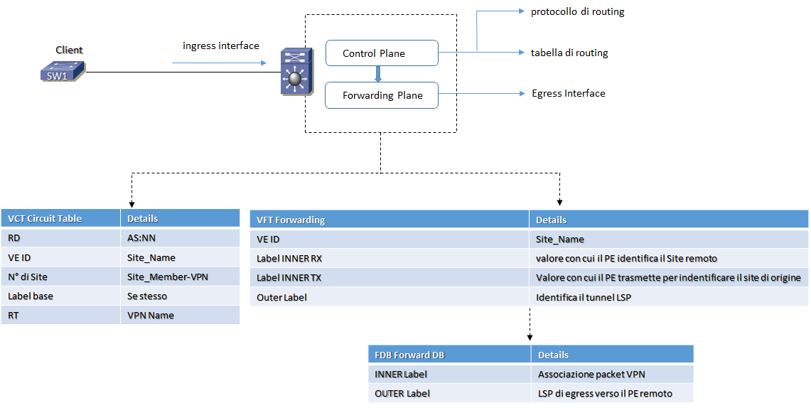
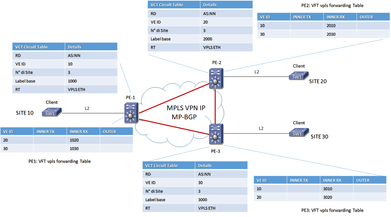
MPLS VPN-L2 VPLS VCT (Virtual Circuit Table)
Un VCT ( Virtual Circuit Table ) contiene le seguenti informazioni:
- – RD Route Distinguisher: analogo alle VPN-L3 indica un indirizzo univoco proprio della VPN (formato AS:NN)
- – VE-ID: un valore intero che identifica in modo univoco il site all’interno della VPN (il numero della site)
- – Numero di site membri della VPN
- – Label base: è il valore di partenza del blocco di inner-label assegnate dal PE router alla VPN in modo dinamico
- – Route Target: analogo alle VPN-L3 è usato per politiche di controllo e filtering di annunci via MP-BGP da parte dei PE routers MPLS
Le VCT sono scambiate tra i PE routers attraverso il protocollo MP-BGP (RFC 2547); attraverso lo scambio della VCT ogni PE router è in grado di realizzare l’auto-discovery degli altri membri
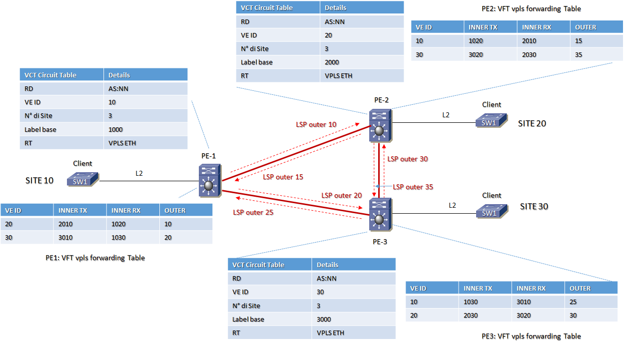
MPLS VPN-L2 VPLS VFT (VPLS Forwarding DataBase)
Il FBD (Forwarding DataBase) è contenuto nell’ambito della VFT (VPLS Forwarding DataBase); oltre alle interfacce fisiche come punti di uscita (egress), sono presenti un certo numero di virtual-ports ognuna delle quali emula una porta ethernet di collegamento verso tutti i PE routers membri del dominio VPLS.
Queste porte partecipano a tutti i meccanismi di learning, forwarding e flooding attivi sulle normali porte degli switch ethernet
Le entry relative ad una porta logica contengono ulteriori informazioni rispetto a quelle di una porta fisica ed in particolare:
- – VE-ID: è la lista di identificativi dei site remoti
- – La inner label da associare alla frame, che nel PE remoto consente a sua volta di associare la frame in ingresso alla specifica VPN-L2 ed al PE router di partenza
- INNER RX: è il valore della inner label che il PE si aspetta di ricevere per tutte le frame provenienti dai site remoti; questa label è usata per demultiplexare i flussi che arrivano ad un egress PE router; per ogni site remoto è assegnata un valore di label con numero progressivo a partire dal numero base (l’inner RX è propagata via MP-BGP agli altri PE routers)
- INNER TX: è il valore della inner label che le frame hanno in direzione di altri PE routers (i valori di inner TX per ogni site remoto sono apprese da un PE attraverso il protocollo MP-BGP)
- – La outer label che individua il tunnel LSP di egress verso il PE router remoto (appresa via LDP oppure RSVP)
MPLS VPN-L2 VPLS VCT + VFT + FDB design
MPLS VPN-L2 VPLS fase 0 design
MPLS VPN-L2 VPLS fase 1 design
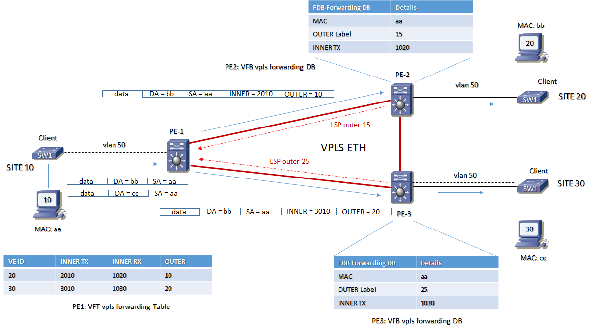
MPLS VPN-L2 VPLS fase 2 design
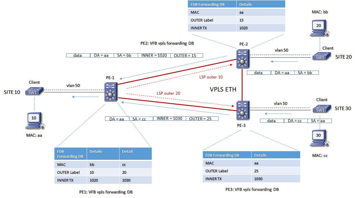
MPLS VPN-L2 VPLS fase 3 design
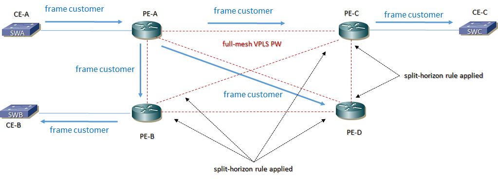
MPLS VPN-L2 VPLS Spanning Tree Avoidance
Non c’è Spanning Tree Protocol all’interno del dominio Core in un Services Provider MPLS per ragioni di loop avoidance in VPLS
La regola split-horizon nel core SP è abilitata di default e nessuna configurazione è necessaria, quindi se una frame customer è ricevuta da un circuito pseudowire, questa non è trasmessa dietro via altro PW.
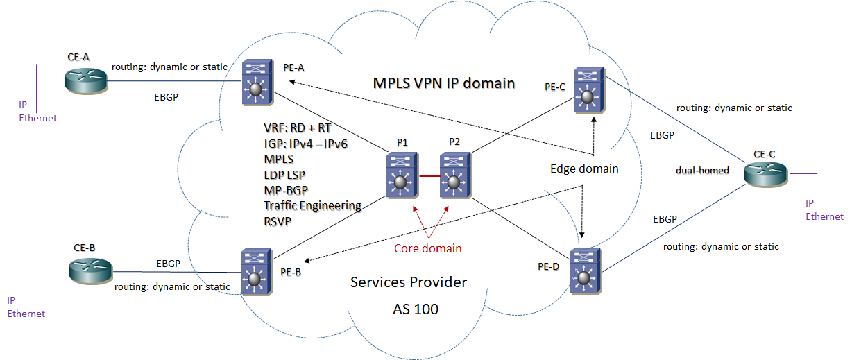
L3VPN Topology Design
L’architettura di riferimento per una topologia L3VPN è la seguente:
MPLS Header
L’informazione è contenuta in un pacchetto MPLS costituito da una o più etichette ( labels );
- Le etichette possono assumere differenti valori ( RFC 3032) di servizio:
- – Label = 0 : IPv4 Explicit Null Label
- – Label = 1 : Router Alert
- – Label = 2 : IPv6 Explicit Null Label
- – Label = 3 : Implicit Null
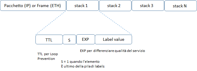
I servizi MPLS hanno tutti a livello dataplane due tipi di labels:
Transport Label: sono etichette con il compito di segnalare il circuito per il pacchetto transitante da un nodo Edge di ingresso ad uno di uscita; generalmente sono delle istruzioni per i nodi di transito tali da istruire questi per dirigere il pacchetto verso il nodo di uscita corretto; in normali condizioni di trasporto la transport label è una sola mentre per applicazioni particolari anche più di una.
Service Label: è un valore di label che identifica il servizio ed è sempre una istruzione per il PE di uscita della rete MPLS per eseguire operazioni quali lookup, trasmissione del payload verso l’interfaccia x; la service label è sempre l’ultima nello stack di labels (S=1)
Entrambe sono annunciate da protocolli quali LDP, RSVP-TE, BGP-LU; è anche possibile l’annuncio di label mpls attraverso protocolli IGP Link-State cone OSPF oppure ISIS via Segment-Routing.
LSP Label Switch Path
- LSP di una rete MPLS può essere considerato analogo ad un PVC (VPI/VCI) di una rete ATM che si instaura tra due end-point routers;
- LSP di una rete MPLS può essere considerato un tunnel in cui transitano pacchetti IP o frame layer 2;
- LSP Hop by Hop è una connessione virtuale creata attraverso un protocollo di routing IGP presente in rete;
- LSP Esplicito è una connessione creata attraverso meccanismi di segnalazione:
- – RSVP: utilizzato per la prenotazione di banda trasmissiva tra due end-point routers
- – CR-LDP: utilizzato nella forma tradizionale MPLS con la distribuzione di labels lungo il percorso LSP