inter-AS option-C with RRs MPBGP vpnv4 tra due differenti AS con rispettivi backbone mpls di cui uno con OSPF multi-area e l’altro con ISIS multi-level configuration and redistribution
10.05 2020 | by massimilianoIl presente documento mette in evidenza la configurazione di un inter-AS option-C tra due backbone appartenenti a diffenti AS e […]
https://www.ingegnerianetworking.com/wp-content/uploads/2020/05/inter-as-c-lab-c10.PNG
Il presente documento mette in evidenza la configurazione di un inter-AS option-C tra due backbone appartenenti a diffenti AS e una serie di output di verifica
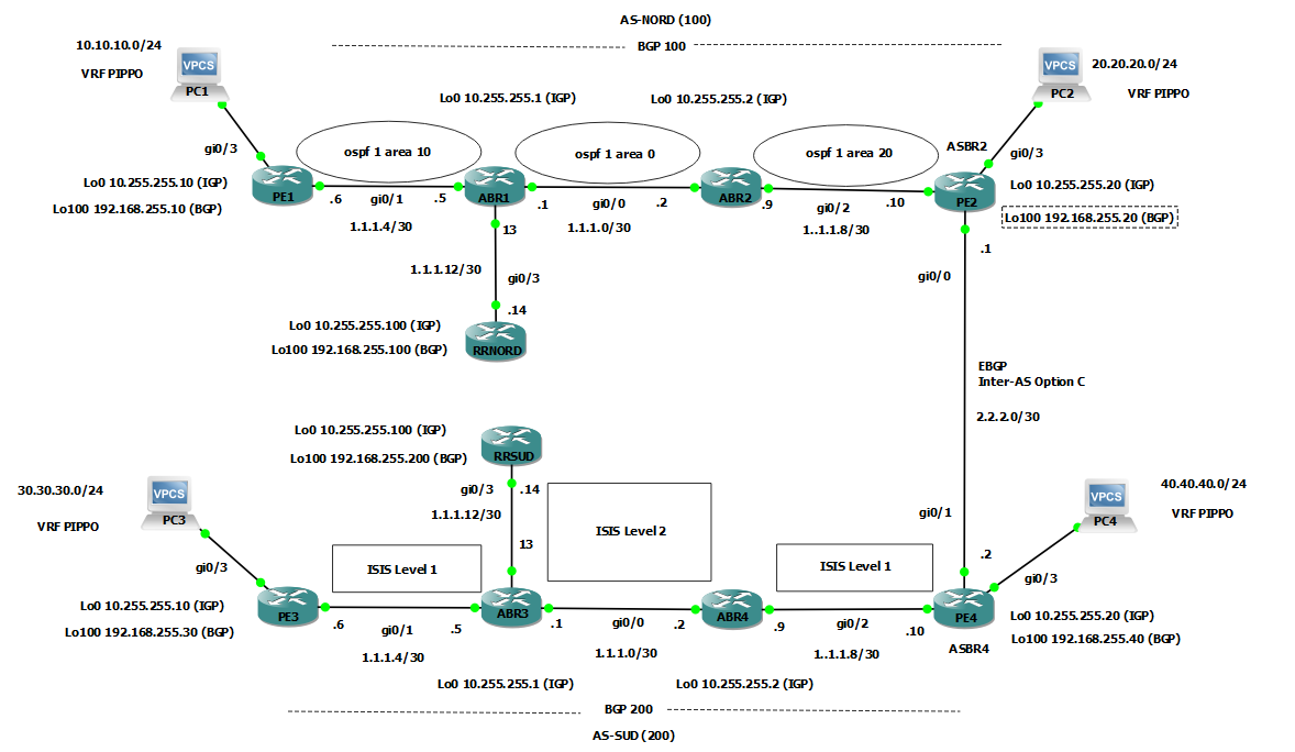
L’architettura di riferimento (lab virtuale) è la seguente:
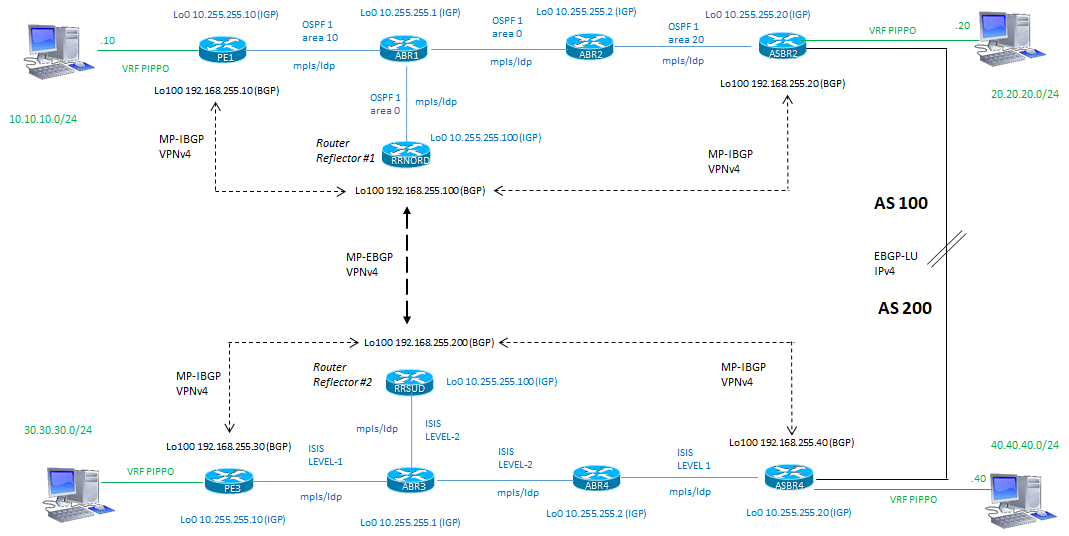
Si riporta anche per maggiore chiarezza la configurazione logica di dettaglio fatta:
Ora (è meglio andare per ordine) si riportano le configurazione per ciascun devices:
Vediamo come il ruolo degli ASBR sono fondamentali a livello di redistribuzione
|
PE1 (AS- 100)
|
PE2/ASBR2 (AS-100) |
|
ip vrf PIPPO rd 100:100 route-target export 100:100 route-target import 100:100 ! mpls label protocol ldp ! interface Loopback0 description Lo0-IGP ip address 10.255.255.10 255.255.255.255 ip ospf 1 area 0.0.0.10 ! interface Loopback100 description Lo100-BGP ip address 192.168.255.10 255.255.255.255 ip ospf 1 area 0.0.0.10 ! interface GigabitEthernet0/1 description to-ABR1 ip address 1.1.1.6 255.255.255.252 ip ospf 1 area 0.0.0.10 mpls ip ! interface GigabitEthernet0/3 description LAN10 ip vrf forwarding PIPPO ip address 10.10.10.1 255.255.255.0 ! router ospf 1 router-id 10.255.255.10 ! router bgp 100 bgp router-id 192.168.255.10 bgp log-neighbor-changes no bgp default ipv4-unicast neighbor 192.168.255.100 remote-as 100 neighbor 192.168.255.100 update-source Loopback100 ! address-family ipv4 exit-address-family ! address-family vpnv4 neighbor 192.168.255.100 activate neighbor 192.168.255.100 send-community extended exit-address-family ! address-family ipv4 vrf PIPPO redistribute connected exit-address-family ! |
ip vrf PIPPO rd 100:100 route-target export 100:100 route-target import 100:100 ! mpls label protocol ldp ! interface Loopback0 description lo0-IGP ip address 10.255.255.20 255.255.255.255 ip ospf 1 area 0.0.0.20 ! interface Loopback100 description lo100-BGP ip address 192.168.255.20 255.255.255.255 ip ospf 1 area 0.0.0.20 ! interface GigabitEthernet0/0 description to-AS200 ip address 2.2.2.1 255.255.255.252 mpls bgp forwarding # questo comando è automatico con il send-label sotto il processo BGP ! interface GigabitEthernet0/2 description to-ABR2 ip address 1.1.1.10 255.255.255.252 ip ospf 1 area 0.0.0.20 mpls ip ! interface GigabitEthernet0/3 description LAN20 ip vrf forwarding PIPPO ip address 20.20.20.1 255.255.255.0 ! router ospf 1 router-id 10.255.255.20 redistribute bgp 100 subnets route-map bgp-to-ospf ! router bgp 100 bgp router-id 192.168.255.20 bgp log-neighbor-changes no bgp default ipv4-unicast no bgp default route-target filter # questo comando è fondamentale vedi nota sotto neighbor 2.2.2.2 remote-as 200 neighbor 2.2.2.2 update-source GigabitEthernet0/0 neighbor 192.168.255.100 remote-as 100 neighbor 192.168.255.100 update-source Loopback100 ! address-family ipv4 neighbor 2.2.2.2 activate neighbor 2.2.2.2 send-community extended neighbor 2.2.2.2 route-map TO-200 in neighbor 2.2.2.2 route-map FROM-100 out neighbor 2.2.2.2 send-label exit-address-family ! address-family vpnv4 neighbor 192.168.255.100 activate neighbor 192.168.255.100 send-community extended exit-address-family ! address-family ipv4 vrf PIPPO redistribute connected exit-address-family ! ip prefix-list FROM-100 seq 5 permit 192.168.255.100/32 ip prefix-list FROM-100 seq 10 permit 192.168.255.10/32 ip prefix-list FROM-100 seq 15 permit 192.168.255.20/32 ! ip prefix-list RRSUD seq 5 permit 192.168.255.200/32 ip prefix-list RRSUD seq 10 permit 192.168.255.30/32 ip prefix-list RRSUD seq 15 permit 192.168.255.40/32 ! ip prefix-list TO-200 seq 5 permit 192.168.255.200/32 ip prefix-list TO-200 seq 10 permit 192.168.255.30/32 ip prefix-list TO-200 seq 15 permit 192.168.255.40/32 ! route-map TO-200 permit 10 match ip address prefix-list TO-200 ! route-map FROM-100 permit 10 match ip address prefix-list FROM-100 ! route-map bgp-to-ospf permit 10 match ip address prefix-list RRSUD set metric-type type-1 ! route-map bgp-to-ospf permit 20 ! |
NOTE:
no bgp default route-target filter: questo comando è fondamentale per disattivare un controllo, (di default è disabilitato a livello RR, ma nel nostro caso l’ASBR non è il RR e non dovrebbe esserlo in generale), per gli annunci di prefix L3VPN tra Autonomous System differenti; senza questo comando le prefix L3VPN (quelle in VRF PIPPO) trasmesse from AS100 (10.10.10.0) to AS200 ed annunciate da un peer interno all’AS200 (RRSUD) sarebbero filtrate e non accettate (scartate)
Invece con il comando specifico di cui sopra abbiamo il seguente output visto da un PE “remoto” in AS200 per una L3VPN annunciata from AS100
PE3#show ip route vrf PIPPO 10.10.10.10
Routing Table: PIPPO
Routing entry for 10.10.10.0/24
Known via “bgp 200”, distance 200, metric 0
Tag 100, type internal
Last update from 192.168.255.10 00:00:28 ago
Routing Descriptor Blocks:
* 192.168.255.10 (default), from 192.168.255.200, 00:00:28 ago
Route metric is 0, traffic share count is 1
AS Hops 1
Route tag 100
MPLS label: 21
MPLS Flags: MPLS Required
PE3#show ip route vrf PIPPO 20.20.20.20
Routing Table: PIPPO
Routing entry for 20.20.20.0/24
Known via “bgp 200”, distance 200, metric 0
Tag 100, type internal
Last update from 192.168.255.20 00:02:51 ago
Routing Descriptor Blocks:
* 192.168.255.20 (default), from 192.168.255.200, 00:02:51 ago
Route metric is 0, traffic share count is 1
AS Hops 1
Route tag 100
MPLS label: 23
MPLS Flags: MPLS Required
Le route-map presenti nell’ASBR settano le loopback dei rispettivi PE e sono le uniche ad essere considerate a livello di redistribuzione via EBGP ipv4 session; le stesse poi debbono essere redistribuite all’interno dei rispettivi processi IGP di routing per una corretta RIB/FIB di ognuno di questi nodi sia PE-router che P-router:
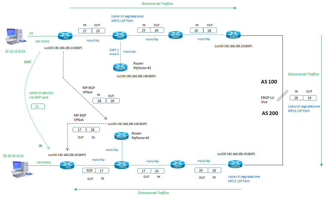
La costruzione di un path LSP end-to-end tra i due AS differenti segue questa logica in diagramma, verificata poi con gli output di riferimento
Esempio:
PE1#show ip route vrf PIPPO
Routing Table: PIPPO
Gateway of last resort is not set
10.0.0.0/8 is variably subnetted, 2 subnets, 2 masks
C 10.10.10.0/24 is directly connected, GigabitEthernet0/3
L 10.10.10.1/32 is directly connected, GigabitEthernet0/3
20.0.0.0/24 is subnetted, 1 subnets
B 20.20.20.0 [200/0] via 192.168.255.20, 03:09:02
30.0.0.0/24 is subnetted, 1 subnets
B 30.30.30.0 [200/0] via 192.168.255.30, 02:06:20
40.0.0.0/24 is subnetted, 1 subnets
B 40.40.40.0 [200/0] via 192.168.255.40, 01:55:41
PE1#show ip route 192.168.255.30
Routing entry for 192.168.255.30/32
Known via “ospf 1”, distance 110, metric 4
Tag 200, type extern 1
Last update from 1.1.1.5 on GigabitEthernet0/1, 02:07:47 ago
Routing Descriptor Blocks:
* 1.1.1.5, from 10.255.255.20, 02:07:47 ago, via GigabitEthernet0/1
Route metric is 4, traffic share count is 1
Route tag 200
PE1#show ip bgp vpnv4 all 30.30.30.30
BGP routing table entry for 100:100:30.30.30.0/24, version 13
Paths: (1 available, best #1, table PIPPO)
Not advertised to any peer
Refresh Epoch 3
200
192.168.255.30 (metric 4) (via default) from 192.168.255.100 (192.168.255.100)
Origin incomplete, metric 0, localpref 100, valid, internal, best
Extended Community: RT:100:100
mpls labels in/out nolabel/21
rx pathid: 0, tx pathid: 0x0
PE1#show mpls forwarding-table
Local Outgoing Prefix Bytes Label Outgoing Next Hop
Label Label or Tunnel Id Switched interface
27 25 192.168.255.30/32 0 Gi0/1 1.1.1.5 # LSP segnalazione path
28 26 192.168.255.200/32 0 Gi0/1 1.1.1.5 # LSP servizio MP-BGP
RRSUD#show mpls forwarding-table
Local Outgoing Prefix Bytes Label Outgoing Next Hop
Label Label or Tunnel Id Switched interface
26 17 192.168.255.30/32 0 Gi0/3 1.1.1.13 # LSP servizio MP-BGP
Questo è il percorso visto dal PE1 al PE3 e sono le label indicate nel diagramma
PE1#traceroute vrf PIPPO 30.30.30.30 source 10.10.10.1
Type escape sequence to abort.
Tracing the route to 30.30.30.30
VRF info: (vrf in name/id, vrf out name/id)
1 1.1.1.5 [MPLS: Labels 25/21 Exp 0] 15 msec 18 msec 14 msec
2 1.1.1.2 [MPLS: Labels 26/21 Exp 0] 13 msec 15 msec 16 msec
3 1.1.1.10 [MPLS: Labels 28/21 Exp 0] 16 msec 15 msec 16 msec
4 2.2.2.2 [MPLS: Labels 19/21 Exp 0] 17 msec 18 msec 11 msec
5 1.1.1.9 [MPLS: Labels 24/21 Exp 0] 15 msec 12 msec 16 msec
6 1.1.1.1 [MPLS: Labels 17/21 Exp 0] 16 msec 16 msec 20 msec
7 30.30.30.1 16 msec 14 msec 14 msec
8 *
30.30.30.30 15 msec 15 msec
Le label in rosso sono quelle di segnalazione LSP Path, quella in verde è la label di servizio per la rete di destinazione
Di seguito vediamo il path LSP che percorre il flusso di traffico tra 10.10.10.10 (sorgente) e 30.30.30.30 (destinazione)
ABR1#show mpls forwarding-table
Local Outgoing Prefix Bytes Label Outgoing Next Hop
Label Label or Tunnel Id Switched interface
25 26 192.168.255.30/32 5030 Gi0/0 1.1.1.2 # LSP di segnalazione Path
ABR2#show mpls forwarding-table
Local Outgoing Prefix Bytes Label Outgoing Next Hop
Label Label or Tunnel Id Switched interface
26 28 192.168.255.30/32 5432 Gi0/2 1.1.1.10 # LSP di segnalazione Path
PE2 / ASBR2 #show mpls forwarding-table
Local Outgoing Prefix Bytes Label Outgoing Next Hop
Label Label or Tunnel Id Switched interface
28 19 192.168.255.30/32 3478 Gi0/0 2.2.2.2 # LSP di segnalazione Path (via EBGP LU IPv4)
Si passa all’altro AS:
PE4 / ASBR4 #show mpls forwarding-table
Local Outgoing Prefix Bytes Label Outgoing Next Hop
Label Label or Tunnel Id Switched interface
19 24 192.168.255.30/32 5768 Gi0/2 1.1.1.9 # LSP di segnalazione Path
ABR4#show mpls forwarding-table
Local Outgoing Prefix Bytes Label Outgoing Next Hop
Label Label or Tunnel Id Switched interface
24 17 192.168.255.30/32 6410 Gi0/0 1.1.1.1 # LSP di segnalazione Path
ABR3#show mpls forwarding-table
Local Outgoing Prefix Bytes Label Outgoing Next Hop
Label Label or Tunnel Id Switched interface
17 Pop Label 192.168.255.30/32 13153 Gi0/1 1.1.1.6 # LSP di segnalazione Path
PE3#show ip bgp vpnv4 vrf PIPPO 30.30.30.0
BGP routing table entry for 100:100:30.30.30.0/24, version 2
Paths: (1 available, best #1, table PIPPO)
Advertised to update-groups:
4
Refresh Epoch 1
Local
0.0.0.0 (via vrf PIPPO) from 0.0.0.0 (192.168.255.30)
Origin incomplete, metric 0, localpref 100, weight 32768, valid, sourced, best
Extended Community: RT:100:100
mpls labels in/out 21/nolabel(PIPPO)
rx pathid: 0, tx pathid: 0x0
Abbiamo visto come il traceroute fatto dal PC1 rispetti l’esatta sequenza label dell’LSP che attraversa i due AS differenti.
Proseguiamo con le configurazioni dei due ABR dell’AS-100
|
ABR1 (AS-100) |
ABR2 (AS-100) |
|
mpls label protocol ldp ! interface Loopback0 description lo0-IGP ip address 10.255.255.1 255.255.255.255 ip ospf 1 area 0.0.0.0 ! interface GigabitEthernet0/0 description to-ABR2 ip address 1.1.1.1 255.255.255.252 ip ospf 1 area 0.0.0.0 mpls ip ! interface GigabitEthernet0/1 description to-PE1 ip address 1.1.1.5 255.255.255.252 ip ospf 1 area 0.0.0.10 mpls ip ! interface GigabitEthernet0/3 description to-RRNORD ip address 1.1.1.13 255.255.255.252 ip ospf 1 area 0.0.0.0 mpls ip ! router ospf 1 router-id 10.255.255.1 ! |
mpls label protocol ldp ! interface Loopback0 description Lo0-IGP ip address 10.255.255.2 255.255.255.255 ip ospf 1 area 0.0.0.0 ! interface GigabitEthernet0/0 description to-ABR1 ip address 1.1.1.2 255.255.255.252 ip ospf 1 area 0.0.0.0 mpls ip ! interface GigabitEthernet0/2 description to-PE2 ip address 1.1.1.9 255.255.255.252 ip ospf 1 area 0.0.0.20 mpls ip ! interface GigabitEthernet0/3 description to-AS200 ip address 2.2.2.1 255.255.255.252 shutdown ! router ospf 1 router-id 10.255.255.2 ! |
Ed ora la configurazione del RR AS-100:
|
RRNORD (AS-100) |
|
mpls label protocol ldp ! interface Loopback0 description lo0-IGP ip address 10.255.255.100 255.255.255.255 ip ospf 1 area 0.0.0.0 ! interface Loopback100 description lo100-BGP ip address 192.168.255.100 255.255.255.255 ip ospf 1 area 0.0.0.0 ! interface GigabitEthernet0/3 description to-BB ip address 1.1.1.14 255.255.255.252 ip ospf 1 area 0.0.0.0 mpls ip ! router ospf 1 router-id 10.255.255.100 ! router bgp 100 bgp router-id 192.168.255.100 bgp cluster-id 10.10.10.10 bgp log-neighbor-changes no bgp default ipv4-unicast neighbor CLIENT peer-group neighbor CLIENT remote-as 100 neighbor CLIENT update-source Loopback100 neighbor 192.168.255.10 peer-group CLIENT neighbor 192.168.255.20 peer-group CLIENT neighbor 192.168.255.200 remote-as 200 neighbor 192.168.255.200 ebgp-multihop 255 neighbor 192.168.255.200 update-source Loopback100 ! address-family ipv4 exit-address-family ! address-family vpnv4 neighbor CLIENT send-community extended neighbor CLIENT route-reflector-client neighbor 192.168.255.10 activate neighbor 192.168.255.20 activate neighbor 192.168.255.200 activate neighbor 192.168.255.200 send-community both neighbor 192.168.255.200 next-hop-unchanged exit-address-family ! |
Passiamo alla configurazione dei nodi dell’AS-200
|
PE3 (AS-200)
|
PE4/ASBR4 (AS-200) |
|
ip vrf PIPPO rd 100:100 route-target export 100:100 route-target import 100:100 ! mpls label protocol ldp ! interface Loopback0 description Lo0-IGP ip address 10.255.255.10 255.255.255.255 ! interface Loopback100 description Lo100-BGP ip address 192.168.255.30 255.255.255.255 ! interface GigabitEthernet0/1 description to-ABR1 ip address 1.1.1.6 255.255.255.252 ip router isis mpls ip isis circuit-type level-1 isis network point-to-point ! interface GigabitEthernet0/3 description LAN10 ip vrf forwarding PIPPO ip address 30.30.30.1 255.255.255.0 ! router isis net 49.0001.0000.0000.0010.00 passive-interface default no passive-interface GigabitEthernet0/1 ! router bgp 200 bgp router-id 192.168.255.30 bgp log-neighbor-changes no bgp default ipv4-unicast neighbor 192.168.255.200 remote-as 200 neighbor 192.168.255.200 update-source Loopback100 ! address-family ipv4 exit-address-family ! address-family vpnv4 neighbor 192.168.255.200 activate neighbor 192.168.255.200 send-community extended exit-address-family ! address-family ipv4 vrf PIPPO redistribute connected exit-address-family ! |
ip vrf PIPPO rd 100:100 route-target export 100:100 route-target import 100:100 ! mpls label protocol ldp ! interface Loopback0 description lo0-IGP ip address 10.255.255.20 255.255.255.255 ! interface Loopback100 description lo100-BGP ip address 192.168.255.40 255.255.255.255 ! interface GigabitEthernet0/1 description to-AS100 ip address 2.2.2.2 255.255.255.252 mpls bgp forwarding ! interface GigabitEthernet0/2 description to-ABR2 ip address 1.1.1.10 255.255.255.252 ip router isis mpls ip isis circuit-type level-1 isis network point-to-point ! interface GigabitEthernet0/3 description LAN20 ip vrf forwarding PIPPO ip address 40.40.40.1 255.255.255.0 ! router isis net 49.0001.0000.0000.0020.00 redistribute bgp 200 route-map bgp-to-isis level-1 passive-interface default no passive-interface GigabitEthernet0/2 ! router bgp 200 bgp router-id 192.168.255.40 bgp log-neighbor-changes no bgp default ipv4-unicast no bgp default route-target filter neighbor 2.2.2.1 remote-as 100 neighbor 2.2.2.1 update-source GigabitEthernet0/1 neighbor 192.168.255.200 remote-as 200 neighbor 192.168.255.200 update-source Loopback100 ! address-family ipv4 redistribute connected redistribute isis level-1-2 route-map isis-to-bgp neighbor 2.2.2.1 activate neighbor 2.2.2.1 send-community extended neighbor 2.2.2.1 route-map TO-100 in neighbor 2.2.2.1 route-map FROM-200 out neighbor 2.2.2.1 send-label exit-address-family ! address-family vpnv4 neighbor 192.168.255.200 activate neighbor 192.168.255.200 send-community extended exit-address-family ! address-family ipv4 vrf PIPPO redistribute connected exit-address-family ! ip prefix-list 100-to-200 seq 5 permit 192.168.255.100/32 ip prefix-list 100-to-200 seq 10 permit 192.168.255.10/32 ip prefix-list 100-to-200 seq 15 permit 192.168.255.20/32 ! ip prefix-list FROM-200 seq 5 permit 192.168.255.200/32 ip prefix-list FROM-200 seq 10 permit 192.168.255.30/32 ip prefix-list FROM-200 seq 15 permit 192.168.255.40/32 ! ip prefix-list TO-100 seq 5 permit 192.168.255.100/32 ip prefix-list TO-100 seq 10 permit 192.168.255.10/32 ip prefix-list TO-100 seq 15 permit 192.168.255.20/32 ! route-map TO-100 permit 10 match ip address prefix-list TO-100 ! route-map FROM-200 permit 10 match ip address prefix-list FROM-200 ! route-map bgp-to-isis permit 20 match ip address prefix-list 100-to-200 ! route-map isis-to-bgp permit 20 ! |
La configurazione degli ABR con ISIS ed in questo caso hanno access-list di redistribuzione tra L2 into L1
| ABR3 (AS-200) | ABR4 (AS-200) |
|
mpls label protocol ldp ! interface Loopback0 description lo0-IGP ip address 10.255.255.1 255.255.255.255 ip router isis ! interface GigabitEthernet0/0 description to-ABR2 ip address 1.1.1.1 255.255.255.252 ip router isis mpls ip isis circuit-type level-2-only isis network point-to-point ! interface GigabitEthernet0/1 description to-PE1 ip address 1.1.1.5 255.255.255.252 ip router isis isis circuit-type level-1 isis network point-to-point ! interface GigabitEthernet0/3 description to-RRSUD ip address 1.1.1.13 255.255.255.252 ip router isis mpls ip isis network point-to-point ! router isis net 49.0001.0000.0000.0001.00 redistribute isis ip level-2 into level-1 route-map L2-L1 passive-interface default no passive-interface GigabitEthernet0/0 no passive-interface GigabitEthernet0/1 no passive-interface GigabitEthernet0/3 no passive-interface Loopback0 ! route-map L2-L1 permit 10 match ip address 10 ! access-list 10 permit 192.168.255.200 access-list 10 permit 192.168.255.20 access-list 10 permit 192.168.255.10 access-list 10 permit 192.168.255.40 ! |
mpls label protocol ldp ! interface Loopback0 description Lo0-IGP ip address 10.255.255.2 255.255.255.255 ! interface GigabitEthernet0/0 description to-ABR1 ip address 1.1.1.2 255.255.255.252 ip router isis mpls ip isis circuit-type level-2-only isis network point-to-point ! interface GigabitEthernet0/2 description to-PE2 ip address 1.1.1.9 255.255.255.252 ip router isis mpls ip isis circuit-type level-1 isis network point-to-point ! router isis net 49.0001.0000.0000.0002.00 redistribute isis ip level-2 into level-1 route-map L2-L1 passive-interface default no passive-interface GigabitEthernet0/0 no passive-interface GigabitEthernet0/2 ! route-map L2-L1 permit 10 match ip address 10 ! access-list 10 permit 192.168.255.200 access-list 10 permit 192.168.255.30 |
Ed infine la configurazione del RRSUD in AS-200
|
RRSUD (AS-200) |
|
mpls label protocol ldp ! interface Loopback0 description Lo0-IGP ip address 10.255.255.100 255.255.255.255 ! interface Loopback100 description Lo100-BGP ip address 192.168.255.200 255.255.255.255 ! interface GigabitEthernet0/3 description to-BB ip address 1.1.1.14 255.255.255.252 ip router isis mpls ip isis circuit-type level-2-only isis network point-to-point ! router isis net 49.0001.0000.0000.0100.00 passive-interface default no passive-interface GigabitEthernet0/3 ! router bgp 200 bgp router-id 192.168.255.200 bgp cluster-id 20.20.20.20 bgp log-neighbor-changes no bgp default ipv4-unicast neighbor CLIENT-SUD peer-group neighbor CLIENT-SUD remote-as 200 neighbor CLIENT-SUD update-source Loopback100 neighbor 192.168.255.30 peer-group CLIENT-SUD neighbor 192.168.255.40 peer-group CLIENT-SUD neighbor 192.168.255.100 remote-as 100 neighbor 192.168.255.100 ebgp-multihop 255 neighbor 192.168.255.100 update-source Loopback100 ! address-family ipv4 exit-address-family ! address-family vpnv4 neighbor CLIENT-SUD send-community extended neighbor CLIENT-SUD route-reflector-client neighbor 192.168.255.30 activate neighbor 192.168.255.40 activate neighbor 192.168.255.100 activate neighbor 192.168.255.100 send-community both neighbor 192.168.255.100 next-hop-unchanged exit-address-family ! |
VERIFICA LATO PC terminali (from PC1 in AS100)
PC1> ping 20.20.20.20
84 bytes from 20.20.20.20 icmp_seq=1 ttl=60 time=6.199 ms
84 bytes from 20.20.20.20 icmp_seq=2 ttl=60 time=7.238 ms
84 bytes from 20.20.20.20 icmp_seq=3 ttl=60 time=4.987 ms
84 bytes from 20.20.20.20 icmp_seq=4 ttl=60 time=5.981 ms
84 bytes from 20.20.20.20 icmp_seq=5 ttl=60 time=7.240 ms
# TO altro AS200
PC1> ping 30.30.30.30
84 bytes from 30.30.30.30 icmp_seq=1 ttl=56 time=12.345 ms
84 bytes from 30.30.30.30 icmp_seq=2 ttl=56 time=11.876 ms
84 bytes from 30.30.30.30 icmp_seq=3 ttl=56 time=11.427 ms
84 bytes from 30.30.30.30 icmp_seq=4 ttl=56 time=12.726 ms
84 bytes from 30.30.30.30 icmp_seq=5 ttl=56 time=11.532 ms
PC1> ping 40.40.40.40
84 bytes from 40.40.40.40 icmp_seq=1 ttl=59 time=7.366 ms
84 bytes from 40.40.40.40 icmp_seq=2 ttl=59 time=8.420 ms
84 bytes from 40.40.40.40 icmp_seq=3 ttl=59 time=7.855 ms
84 bytes from 40.40.40.40 icmp_seq=4 ttl=59 time=8.644 ms
84 bytes from 40.40.40.40 icmp_seq=5 ttl=59 time=8.103 ms
# TO stesso AS-100
PC1> trace 20.20.20.20
trace to 20.20.20.20, 8 hops max, press Ctrl+C to stop
1 10.10.10.1 1.973 ms 2.657 ms 1.751 ms
2 1.1.1.5 7.966 ms 6.005 ms 5.033 ms
3 1.1.1.2 7.871 ms 7.816 ms 8.753 ms
4 20.20.20.1 6.679 ms 6.907 ms 6.327 ms
5 *20.20.20.20 11.153 ms (ICMP type:3, code:3, Destination port unreachable)
PC1>
PC1>
# TO altro AS200
PC1> trace 30.30.30.30
trace to 30.30.30.30, 8 hops max, press Ctrl+C to stop
1 10.10.10.1 1.947 ms 2.082 ms 1.596 ms
2 1.1.1.5 13.125 ms 14.382 ms 14.218 ms
3 1.1.1.2 14.713 ms 12.992 ms 17.403 ms
4 1.1.1.10 15.191 ms 19.014 ms 27.881 ms
5 2.2.2.2 17.181 ms 17.181 ms 17.386 ms
6 1.1.1.9 18.381 ms 18.239 ms 12.999 ms
7 1.1.1.1 16.489 ms 15.880 ms 13.843 ms
8 30.30.30.1 15.717 ms 17.358 ms 16.051 ms
PC1>
PC1> trace 40.40.40.40
trace to 40.40.40.40, 8 hops max, press Ctrl+C to stop
1 10.10.10.1 2.240 ms 2.643 ms 2.073 ms
2 1.1.1.5 12.178 ms 14.603 ms 13.573 ms
3 1.1.1.2 12.026 ms 17.568 ms 11.956 ms
4 1.1.1.10 17.511 ms 12.239 ms 10.252 ms
5 40.40.40.1 15.382 ms 25.981 ms 13.681 ms
6 *40.40.40.40 9.558 ms (ICMP type:3, code:3, Destination port unreachable)
PC1>
VERIFICA LATO PC terminali (from PC3 in AS200)
PC3> ping 40.40.40.40
84 bytes from 40.40.40.40 icmp_seq=1 ttl=60 time=6.820 ms
84 bytes from 40.40.40.40 icmp_seq=2 ttl=60 time=6.817 ms
84 bytes from 40.40.40.40 icmp_seq=3 ttl=60 time=6.101 ms
84 bytes from 40.40.40.40 icmp_seq=4 ttl=60 time=6.647 ms
84 bytes from 40.40.40.40 icmp_seq=5 ttl=60 time=5.002 ms
PC3>
TO altro AS100
PC3> ping 10.10.10.10
84 bytes from 10.10.10.10 icmp_seq=1 ttl=56 time=12.917 ms
84 bytes from 10.10.10.10 icmp_seq=2 ttl=56 time=19.441 ms
84 bytes from 10.10.10.10 icmp_seq=3 ttl=56 time=12.301 ms
84 bytes from 10.10.10.10 icmp_seq=4 ttl=56 time=12.594 ms
84 bytes from 10.10.10.10 icmp_seq=5 ttl=56 time=10.481 ms
PC3>
PC3> ping 20.20.20.20
84 bytes from 20.20.20.20 icmp_seq=1 ttl=59 time=8.455 ms
84 bytes from 20.20.20.20 icmp_seq=2 ttl=59 time=7.482 ms
84 bytes from 20.20.20.20 icmp_seq=3 ttl=59 time=8.877 ms
84 bytes from 20.20.20.20 icmp_seq=4 ttl=59 time=7.626 ms
84 bytes from 20.20.20.20 icmp_seq=5 ttl=59 time=9.491 ms
PC3>
TRACE all’interno dello stesso AS200
PC3> trace 40.40.40.40
trace to 40.40.40.40, 8 hops max, press Ctrl+C to stop
1 30.30.30.1 2.424 ms 2.010 ms 2.212 ms
2 1.1.1.5 7.193 ms 6.399 ms 6.723 ms
3 1.1.1.2 8.968 ms 6.745 ms 5.842 ms
4 40.40.40.1 8.996 ms 8.484 ms 8.520 ms
5 *40.40.40.40 5.895 ms (ICMP type:3, code:3, Destination port unreachable)
PC3>
PC3>
TRACE TO altro AS100:
PC3> trace 10.10.10.10
trace to 10.10.10.10, 8 hops max, press Ctrl+C to stop
1 30.30.30.1 2.530 ms 1.935 ms 1.806 ms
2 1.1.1.5 11.776 ms 14.282 ms 16.717 ms
3 1.1.1.2 14.817 ms 13.712 ms 13.553 ms
4 1.1.1.10 14.410 ms 15.972 ms 13.297 ms
5 2.2.2.1 14.941 ms 12.833 ms 12.415 ms
6 1.1.1.9 15.652 ms 13.458 ms 14.293 ms
7 1.1.1.1 16.229 ms 16.286 ms 14.304 ms
8 10.10.10.1 19.697 ms 16.347 ms 16.033 ms
PC3>
PC3>
PC3> trace 20.20.20.20
trace to 20.20.20.20, 8 hops max, press Ctrl+C to stop
1 30.30.30.1 1.738 ms 2.408 ms 1.802 ms
2 1.1.1.5 8.616 ms 8.088 ms 9.041 ms
3 1.1.1.2 8.254 ms 9.164 ms 13.804 ms
4 1.1.1.10 11.394 ms 9.359 ms 9.782 ms
5 20.20.20.1 17.692 ms 11.033 ms 10.215 ms
6 *20.20.20.20 7.937 ms (ICMP type:3, code:3, Destination port unreachable)
PC3>