SDA cisco: DNA CENTER Provisioning OVERLAY with LAN Automation (step)
16.02 2024 | by massimilianoSD-Access supporta la seguente orchestrazione: IP-based transit di solito utilizza sistemi con VRF-lite per la connettività verso external networks. SD-Access […]
SD-Access supporta la seguente orchestrazione:
- Fabric Site: significa una Fabric indipendente che include dei Control-Plane Node, Edge Node per le funzionalità di accesso, Border Node per funzionalità di Egress Fabric Site ed infine sistemi quali ISE e WLC fabric mode.
- Transit Site or Network: riferito a collegamenti tra la Fabric ed External Domain (conosciuti come IP-based transit) oppure tra uno o più Fabric Site preservando comunque tra questi le policy di segmentazione (conosciuti come SD-Access transit)
- Fabric Domain: riguarda un unico dominio di amministrazione che abbraccia uno o piu site ed i corrispondenti transit network.
IP-based transit di solito utilizza sistemi con VRF-lite per la connettività verso external networks.
SD-Access transit trasporta SGT (micro-segmentation) e VNs information (macro-segmentation) tra Fabric site, creando di fatto un campus distribuito.
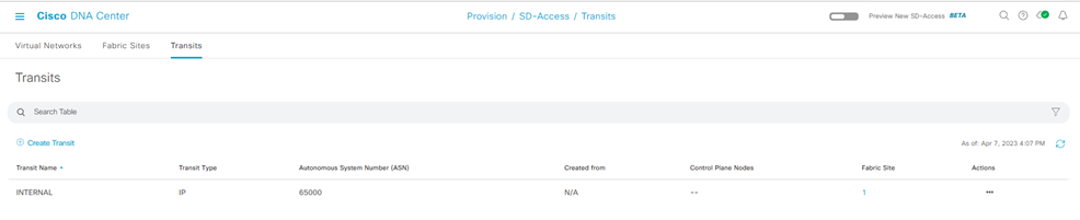
Network Transit
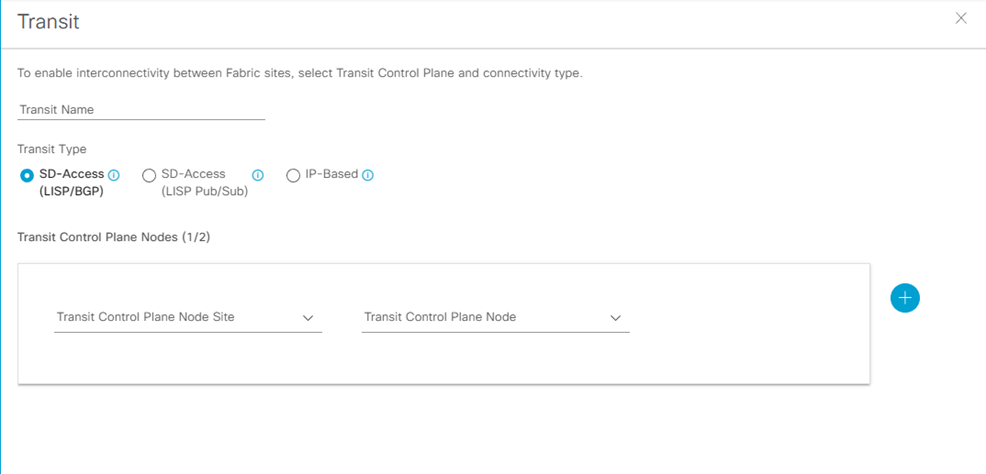
Step-1: navigate to Provision > Transit > Create Transit
Enter
- Transit Name:
- Transit Type [ SD-Access LISP/BGP; SD-Access LISP Pub/Sub; IP-Based ]:
- Transit Control Plane Nodes Sites – Transit Control Plane Node
- Protocol: BGP
- Autonomous System Number:
Fabric Domain, Fabric Site
Step-1: navigate to Provision > Fabric Site > Create Fabric Sites and Fabric Zone
La Fabric Infrastructure mostra un’architettura a due livelli (access-distribution) oppure a tre livelli (access-distribution-core).
La Host Onboarding evidenzia le seguenti funzionalità:
- Authentication Template
- Virtual Networks
- Wireless SSID
- Port Assignment
Fabric Control Plane Node Roles
I nodi con funzionalità di Control Plane Node (senza il ruolo di Border Node), necessitano di essere assegnati come CP (Control Plane).
Per questo è sufficiente selezionare il nodo (hostname), click su esso eppoi nel popup box, click su Add as CP.
Fabric Border Node Roles
I nodi con funzionalità di Border Node hanno necessità di assegnare ad essi differenti funzionalità, quali:
Step-1:
click sul nodo hostname
- Add as Border or Add as CP+Border
Under Layer 3 Handoff
- Select Border
- Supply BGP Local Autonomous Number
Under Select IP Address Pool
- Choose the global IP pool configured previously for border connectivity
For External Border
- Click Is this site connected to Internet?
Transit
- Select the transit
Add button
Step-2:
Click IP Transit text
Click + Add Interface (in the box select the interface for the connection to the fusion router outside Fabric
Below the BGP ASn expand the Virtual Network and select each VN used in the Fabric to include in the Layer 3 Handoff outside the Fabric
Click Save
Click Add
In caso di più Fabric Border Node, ripetere i precedenti due steps.
Dopo che tutti i roles sono stati assegnati, click Save, use the default choise Now, and then click Apply.
Il Fabric Domain è creato.
Fabric Layer 2 Border Node (MIgration Process)
Per processi di migrazione tra una architettura ASIS verso SDA Fabric, vengono utilizzati dedicati Fabric Layer 2 Border per semplificare la transizione layer 2 da vlan tradizionali a fabric-enabled vlan.
Questi nodi, difatti, traducono la vlan tradizionale in una fabric-enabled vlan all’interno della Fabric.
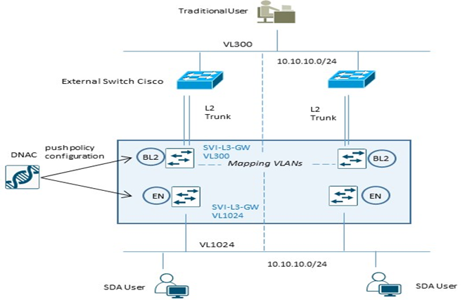
| Example Configuration Fabric Edge Node (VL1024) | Example Configuration Fabric L2 Border Node (VL300) |
| instance-id 8188 remote-rloc-probe on-route-change service ethernet eid-table vlan 1024 broadcast-underlay 239.0.0.1 database-mapping mac locator-set xxx exit service-ethernet exit instance-id interface vlan 1024 description mapping vlans1024-300 mac-address 0000.0c9f.f45c vrf forwarding Migration ip address 10.10.10.1 255.255.255.0 ip helper-address 10.100.100.101 no ip redirects ip route-cache same-interface no lisp mobility liveness test lisp mobility 1024_300_MIGRATION | instance-id 8188 remote-rloc-probe on-route-change service ethernet eid-table vlan 300 broadcast-underlay 239.0.0.1 database-mapping mac locator-set xxx exit service-ethernet exit instance-id interface vlan 300 description mapping vlans1024-300 mac-address 0000.0c9f.f45c vrf forwarding Migration ip address 10.10.10.1 255.255.255.0 ip helper-address 10.100.100.101 no ip redirects ip route-cache same-interface no lisp mobility liveness test lisp mobility 1024_300_MIGRATION |
Nota:
Layer 2 Border Node non supporta configurazioni multihomed; permette solo collegamenti verso switch non-fabric in access mode oppure trunk mode per singolo external devices.
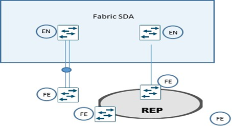
Extended Node
Extended Node sono particolari nodi layer 2 connessi sempre ad un Fabric Edge node, che collegano sistemi quali IoT e/o altri, performano 802.1x oppure MAB authentication.
Asegnazione di vlans sono possibili attraverso ISE, ma un SGT value non può essere assegnato ad un extended node; gli end-user connessi ad un extended node sono comunque gestiti da DNAC attraverso una policy statica VLAN-to-SGT configurata e mappata su un Edge Node, il quale node performa i protocolli LISP (rloc-ied), VXLAN e SGT (scalable group access control).
Un extended node può gestire traffico multicast per la sola ricezione dei pacchetti per receiver ad esso collegati.
La modalità di collegare un extended node alla Fabric SDA sono via un port-channel connesso ad un singolo Fabric Edge,
Il port-channel supporta PAgP (Port Aggregation Protocol).
Un altro metodo è riferito al ring REP (Resilient Ethernet Protocol) molto usato per fast convergence, resiliency and HA.
STEP-1: apply device credential (CLI and SNMP settings) at site level whee the extended node need to be provisioned from DNAC (Design > Network Hierarchy);
STEP-2: add an IP address pool for the extended node management; if the extended node is provisioned via PnP automatically onbording, configure an IP pool for DNAC to assign a loopback interface address for the discovery process;
STEP-3: Reserve an IP pool for the IoT client connected to extented node at fabric site level where the extended node is assigned;
STEP-4: create a VN (virtual network) for pool IoT devices for security reason if required; VN creation is not necessary if the IoT devices will be part of the existing VN as the campus users (SGTs leverage to apply segmentation policies if the IoT devices are in the same VN as campus user);
STEP-5: configure a port-channel on Fabric Edge for th extended node link;
STEP-6: assign the extended node management IP address pool (created in step-2) under Privision > Fabric Sites > Host Onboarding > Virtual Network section and click INFRA_VN
Click Pool Type and choose Extended.
Questa operazione permette l’inserimento dell’extended node come device di infrastruttura e posizionato nella INFRA_VN (simile a quanto succede per gli AP) e risulterà una SVI creata per l’IP pool stesso.
Fabric Multicast Enable
Questa procedura prevede la configurazione del native-multicast:
Assumption:
- SD-Access supporta ASM e SSM
- Sources possono essere all’interno delle VN oppure fuori Fabric
- Rendezvous Point dovrebbero essere configurati a livello di Border Node
- PIM messages sono unicast tra Border ed Edge node
- I pacchetti multicast sono replicati a livello di head-end Border devices verso la parte di Edge nodes.
Step-1: navigate to Design > Network Settings > IP address pool
Create a pool under the global site hierarchy and reserve the pool in the respective site
Un global pool è dedicato per unicast IP loopback interfaces in overlay VN con multicast enabled per la trasmissione di PIM Join
Step-2: navigate to: Provision > Fabric Site > click on Fabric Border Node > select Enable Rendezvous Point.
Step-3: all’interno del match Associate Multicast Pool to VNs, sotto Associate Virtual Networks, scegliere la VN e sotto Select IP Pool, scegliere il pool creato per il Muslticast, click Next eppoi Enable.
Step-4: ripetere i precedenti steps per eventuali altri Fabric Node; click Save eppoi Apply.
DNA-Center prevede la configurazione per il Multicast sui Border Node, crea le loopback con MSDP peering attivo per il Rendezvous Point state communication tra Border Node.
Step-5: in caso di multicast MSDP peering all’esterno rispetto ai Border Node verso il Fusion Router, settare la seguente configurazione per ogni Border Node:
Global level:
ip multicast-routing
ip pim rp address < RP address >
ip pim register-source loopback0
ip pim ssm default
Interface level:
ip pim sparse-mode
Step-6: enable Native Multicast for IPv4 > Save > leave the default selection of Now > click Apply.