ACI: ipotesi multisite architecture and best-pratices configuration deployment
19.02 2024 | by massimilianoIpotesi 1: ISN/IPN unico dominio multisite Ipotesi 2: ISN/IPN mutua-redistribuzione multisite Ipotesi 3: MPBGP EVPN L3OUT GOLF multisite Multisite Cluster […]
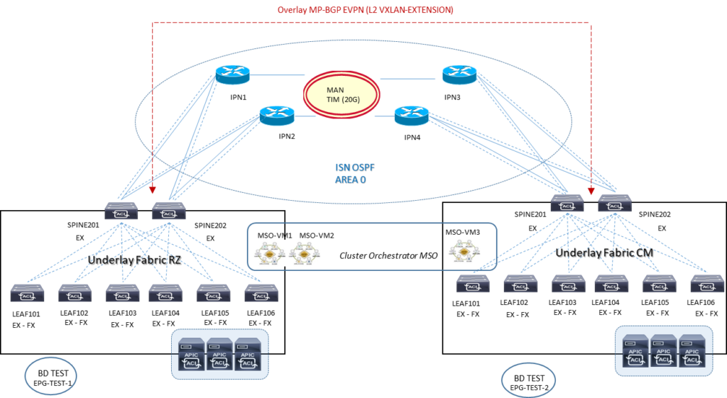
Ipotesi 1: ISN/IPN unico dominio multisite
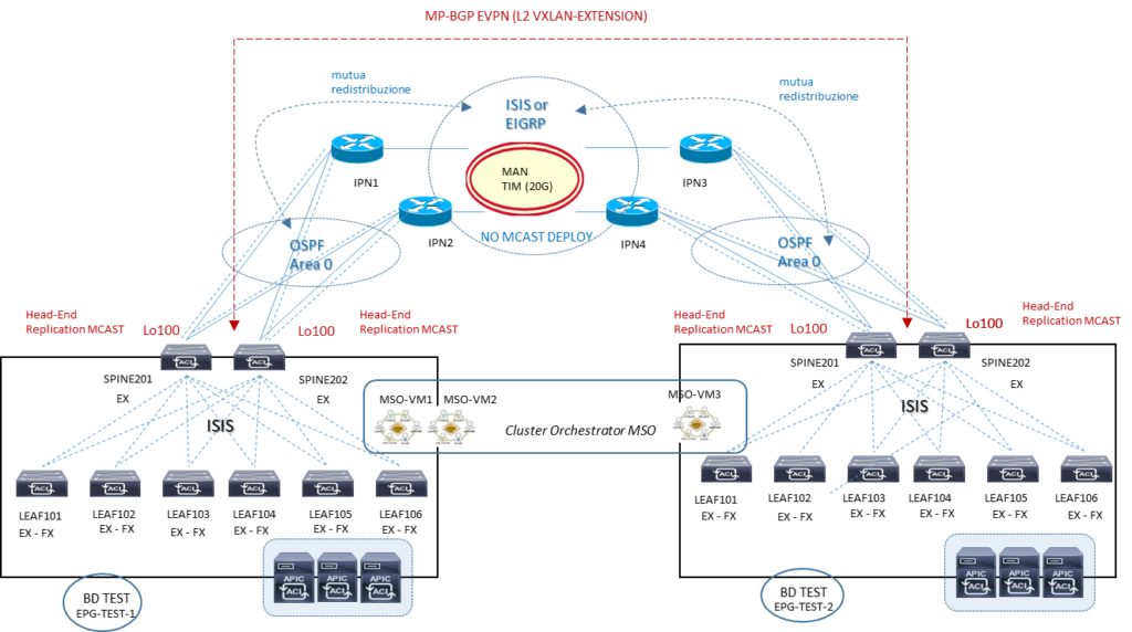
Ipotesi 2: ISN/IPN mutua-redistribuzione multisite
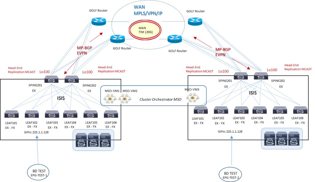
Ipotesi 3: MPBGP EVPN L3OUT GOLF multisite
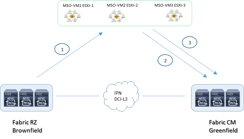
Multisite Cluster APIC Deployment
Connect the Multi-Site cluster to the APICs using the OOB management network.
The Multi-Site cluster should never be deployed within a Cisco ACI fabric that it is managing as a site. It should always be deployed outside the Cisco ACI fabric (for example, connected to the OOB network). Otherwise, double failures can occur if the Multi-Site cluster fails or the Cisco ACI fabric fails.
Each Multi-Site virtual machine should have a routable IP address, and all three virtual machines must be able to ping each other. This setup is required to form a Docker swarm cluster.
Deploy one Multi-Site virtual machine per ESXi host for high availability. The virtual machines will form a cluster among themselves through a Docker swarm.
The maximum RTT between the virtual machines in a cluster should be less than 150 ms.
The maximum distance from a Multi-Site cluster to a Cisco ACI fabric site can be up to 1 second RTT
A Multi-Site cluster uses the following ports for the internal control plane and data plane, so the underlay network should always ensure that these ports are open (in the case of an ACL configuration of a firewall deployment in the network):
TCP port 2377 for cluster management communication
TCP and UDP port 7946 for communication among nodes
UDP port 4789 for overlay network traffic
TCP port 443 for Multi-Site policy manager User Interface (UI)
IP 50 Encapsulating Security Protocol (ESP) for encryption
IPsec is used to encrypt all intra–Multi-Site cluster control-plane and data-plane traffic to provide security because the virtual machines can be placed up to 150 ms RTT apart.
The minimum specifications for Multi-Site virtual machines are ESXi 5.5 or later, four vCPUs, 8 GB of RAM, and a 5-GB disk.
Multisite VMM Deployment
VMM domains can be integrated into a Cisco ACI Multi-Site architecture. Separate VMM domains are created at each site because the sites have separate APIC clusters
Those VMM domains can then be exposed to the ACI Multi-Site policy manager in order to be associated to the EPGs defined there
Multiple VMMs can be used across separate sites, each paired with the local APIC cluster
A single VMM can be used to manage hypervisors deployed across sites and paired with the different local APIC clusters
The VMM at each site manages the local hosts and peers with the local APIC domain to create a local VMM domain
The configuration of the VMM domains is performed at the local APIC level. The created VMM domains can then be imported into the Cisco ACI Multi-Site policy manager and associated with the EPG specified in the centrally created templates
- for example, EPG 1 is created at the Multi-Site level, it can then be associated with VMM domain DC1 and with VMM domain DC2 before the policy is pushed to Sites 1 and 2 for local implementation
The creation of separate VMM domains across sites usually restricts the mobility of virtual machines across sites to cold migration scenarios. However, in specific designs using VMware vSphere 6.0 and later, you can perform hot migration between clusters of hypervisors managed by separate vCenter Servers
vCenter Server Release 6.0 or later is the only VMM option that allows live migration across separate Cisco ACI fabrics. With other VMMs SCVMM, and OpenStack deployments, if you want to perform live migration, you must deploy the VMMs in a single Cisco ACI fabric (single pod or Multi-Pod)
Multisite Day-0 Infrastructure Deployment
All the physical interfaces connecting the spine nodes to the intersite network must be on Cisco Nexus EX platform line cards (or a newer generation). Generation-1 spine nodes are not supported and can be used only for intra-fabric communication.
The APIC fabric ID in a Multi-Site deployment can be unique, or the same value can be used across sites for greenfield or brownfield deployments. In scenario where shared GOLF devices are not deployed between different sites, the recommendation is to keep the Fabric ID 1 across all sites. If shared GOLF is required (once supported) there are theree possible scenarios:
1.Auto-RT is not configured: the recommendation is to keep Fabric ID 1 across all sites.
2.Auto-RT is enabled and the sites are part of unique BGP ASN: the recommendation is to keep Fabric ID 1 across all sites.
3.Auto-RT is enabled and the sites are part of the same BGP ASN: the recommendation is to use unique fabric IDs across sites
APIC New Greenfield = each new APIC should exist in a POD; If you have a three-APIC cluster and you want to move one APIC to a new data center, then the best approach is to decommission this APIC, clean the configuration, and move the APIC to the new data center (pod) to be reconfigured in that different pod.
APIC Existing Brownfield = includes newly added and configured APIC fabric in a new data center and pod location, with the new pod ID and appropriate configuration
The Cisco ACI Multi-Site site ID or site name must be unique across all sites. This parameter is configured directly on the Multi-Site policy manager.
The Cisco ACI Multi-Site site ID (not the site name) cannot be changed after it has been assigned. To reconfigure the site ID, you will need to perform a clean wipe to return to the factory defaults.
Note: The APIC site ID is different from the Cisco ACI fabric ID assigned on the APIC
In ACI Multi-Site, always undeploy a schema-template from a site before removing from a site.
The configured fabric TEP pools should be unique and not overlapping across sites.
All Multi-Site control-plane and data-plane TEPs should be externally routable over ISN.
Four types of TEP addresses need to be configured
CP-ETEP Control-Plane External Tunnel Endpoint = this unique IP address is defined on each spine node belonging to a fabric and is used to establish MP-BGP EVPN adjacencies with the spine nodes in remote pods; the “ E ” refers to the fact that the IP addresses must not be part of the TEP pool defined at a given site and should instead be “external” and, if needed, globally routable (because different sites may be interconnected by public Layer 3 networks).
DP-ETEP Data-Plane External Tunnel Endpoint = this common anycast address is shared by all the spine nodes at the same site and is used to source and receive unicast VXLAN data-plane traffic. Each site is characterized by a DP-ETEP address that essentially uniquely identifies the site.
HER-ETEP Head-End Replication External Tunnel Endpoint = this common anycast address is shared by all the spine nodes in the same site and is used to perform head-end replication for BUM traffic.
BUM traffic is sourced from the HER-DTEP address defined on the local spine nodes and destined for the HER-DTEP of remote sites to which the given bridge domain is being stretched.
Multi-Pod data-plane TEP: Configure this address directly on each APIC cluster in Cisco ACI Release 3.0.
◦ This configuration is mandatory even if Multi-Pod fabrics are not initially supported in a Cisco ACI Multi-Site architecture; This address will be configurable from the Cisco ACI Multi-Site deployment after Multi-Pod and Multi-Site support are added in the future.
External data-plane multicast TEP (HER-ETEP):
◦ This address is used as the destination IP address for BUM traffic sent across the fabric in head-end replication (or HER) mode.
External data-plane unicast TEP (DP-ETEP):
◦ This address is used as the anycast VTEP address for each pod.
◦ Configure one address per pod.
◦ This address is used as the next-hop on the local spine node to reach remote endpoints.
◦ In Cisco ACI Release 3.0, the same IP address can be configured as Multi-Site DP-ETEP and MultiPod data-plane TEP.
External control-plane TEP (CP-ETEP):
◦ This address is used to form MP-BGP EVPN sessions.
◦ Define one unique IP address per spine node.
Allocate at least two spine nodes for Multi-Site BGP-EVPN peering in an Cisco ACI pod (for redundancy). Note that not all the spine nodes need to be BGP-EVPN peers.
We recommend use full-mesh BGP-EVPN peering instead of route reflectors since it represents a simpler approach, and at FCS only five sites are supported, so full-mesh peering is fine to use. BGP-EVPN will automatically form full-mesh iBGP and eBGP peerings.
When route reflectors are used, they will apply to iBGP sessions only within the Autonomous System Number (ASN), and eBGP will still use full mesh between ASNs. A spine node can support both types of peering at the same time.
When deploying Route Reflector (RR) with high availability for N sites, you can deploy 1 RR instance on a spine node in a site and deploy this across 3 sites which would cover high availability requirement for N sites instead of deploying 1 RR instance in every site.
Use BGP and OSPF default general settings for Multi-Site ISN.
Check to ensure that the Time-To-Live (TTL) setting is large enough if the sessions are eBGP (the default is 16).
Make sure that the source interface for the intersite BGP-EVPN sessions is configured with the control-plane TEP (with the infra L3Out connection assigned to the right loopback connector).
Use separate infra L3Out connections for GOLF and Multi-Site connectivity. The infra L3Out connection used for GOLF must be configured directly on the APIC (it can’t be configured in the Multi-Site policy manager).
Verify that the secure BGP passwords match in the various sites (if configured).
The BGP community sample format is extended:as2-nn4:4:15
General Best-Practices Deployment
If WAN connectivity is over GOLF, you need to consider two scenarios:
Scenario 1:
Site 1 has its own non-stretched BD1 and Subnet 1 and GOLF L3Out-1 connection, and Site 2 has its own non-stretched BD2 and Subnet 2 and GOLF L3Out-2 connection.
Each GOLF L3Out connection advertises its own bridge domain subnet to its own GOLF router, so host routing is not required.
Scenario 2:
BD1 and Subnet 1 is stretched to Sites 1 and 2.
The Layer 2 stretch flag is enabled.
Inter-Site_BUM_Traffic_Allow can be enabled or disabled.
Each site also has its own local GOLF L3Out connection, which advertises the subnet through its GOLF L3Out connection to its GOLF router. ° The subnet in the WAN will have an equal-cost multipath (ECMP) path to the two GOLF routers.
To avoid suboptimal routing of traffic across sites, host routing can be used for stretched bridge domain and subnet cases.
Suboptimal routing of GOLF traffic over IPN is not supported. This means that traffic cannot be delivered from the GOLF router to a specific site and then be redirected to a separate site to reach a remote destination endpoint.
Intersite VXLAN tunnels must transit through the ISN and cannot use another site for transit. As a consequence, you must build enough redundancy into the ISN to help ensure that two given sites are always connected through the ISN in any node or link failure scenario.
Each site must deploy a local L3Out connection:
◦ A site cannot provide transit routing services for a different site.
◦ A pair of WAN edge routers can be shared across sites (traditional L3Out connection on border leaf nodes).
◦ Shared WAN edge routers across sites are not supported in the first Cisco ACI Multi-Site release when GOLF L3Out connections are deployed.
A Multi-Pod fabric is not supported as a site in the initial Cisco ACI Multi-Site release.•Domain (VMM and physical) definition and association is performed at the site level.
Domain (VMM and physical) definition and association is performed at the site level.
Policies pushed to a site from a Multi-Site deployment can be modified locally in the APIC. A warning will appear in the Multi-Site policy manager if the policy implemented for a site is different from the policy specified in the Multi-Site template.
Quality-of-Service (QoS) marking in the WAN is not supported when intra-EPG isolation or microsegmentation is configured
Without any QoS policies configured at a site, the default DSCP value of the outer IP address of the VXLAN packet in the ISN is set to 0. You should configure a QoS DSCP marking policy on the spine node to help ensure proper QoS treatment in the ISN.
Each tenant or VRF instance must have its own L3Out connection. With shared L3Out connections, one L3Out connection would be shared across multiple VRF instances, but this setup is not supported
A Multi-Site deployment can be enabled only when at least one spine interface is connected to the ISN.
◦ If a spine port is connected to the ISN and peering is disabled, only the data plane is enabled on that spine node.
◦ If a spine port is connected to the ISN and peering is enabled, control-plane BGP-EVPN sessions are formed across spine nodes and across sites that have peering enabled through control-plane TEPs.
BGP-EVPN convergence for route-reflector or full-mesh scenarios with iBGP, eBGP, or a hybrid (iBGP plus eBGP) is typically <= 1 second in lab environments for medium-size deployments. However, <= 5 seconds for convergence in real medium-size deployments is common due to external factors such as the WAN.
The Multi-Site fabric discovers pods and EX-platform spine line card information from the APIC and updates the infra configuration.
All available infra configurations are retrieved from the APIC of the site being created from the managed objects, and the Multi-Site configuration is auto-populated.
MSO Orchestrator Best-Practices policies
1.Import existing tenant policies from site RZ into a multisite template
2.Apply the template to site CM
3.Push the template to site CM